NOTE: I am not at liberty to redistribute the documentation used to build this model.
2015 F-22 "Raptor" High Resolution Project
Exterior Shaping:
Exterior Shaping:
The act of remodeling this aircraft in Psubs has already proved to be interesting and informative. When I originally built in in the late 1990s, I was quite happy to have something that simply matched what I thought was the exterior outline. As hardware and software have improved over the years, I’m now able to focus more on precision, and especially the small details.
My initial thought was that every part would either have to be built from scratch, or that a very dense model would have to be built, then overlaid with the sawtooth-edged panels, each carefully crafted with edge weighting. For some parts of the airframe, this may still be the best method. But, for major airframe parts such as the flying surfaces, which are built from large metal and/or composite panels in real life, I’ve come up with a much faster method that produces great results.
Using the wings as the example:
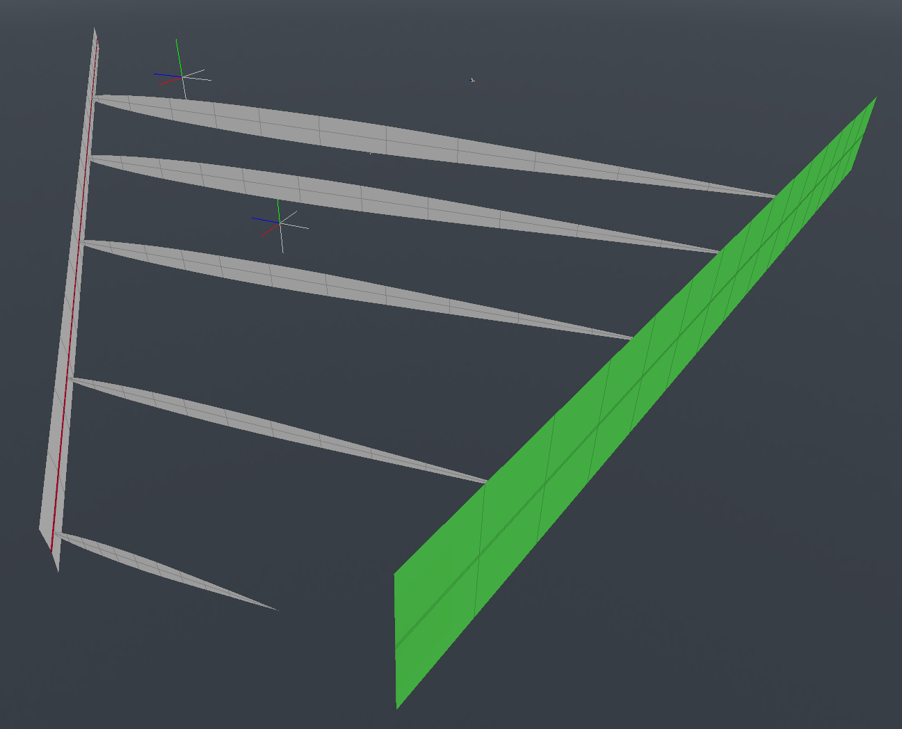
First, I was especially careful in creating the overall shape. I did this by using one of the airfoils that is claimed to be similar to the ones used on the actual aircraft. (NACA 64A004) I traced this in MODO over a backdrop image, and then duplicated it four times, giving me five sections to work with. These were scaled to 80% of their actual thickness, after a lot of trial and error, which looked about right, based on both the reference drawings and photos. I then scaled their overall size to match the shape in the top view. Finally, I rotated each one to a different angle of attack, to create the wing twist and taper (washout) of the actual wings. Bridging their edges produced the wing shape, and adding a bit of edge-weighting keeps them sharp at the corners. This took several iterations, until I was satisfied that I had the right shape, and the time spent was worth it, because if the overall shape isn’t right, then it won’t match with the fuselage properly, and also, the control surfaces and everything that follows will be wrong too.
The wing setup: The green-colored guide in the image is just to show me a horizontal line, so I could keep an eye on the trailing edge twist. The more important guide in the front, with the red polygons, shows me where the nose of each rib needs to go, in order to preserve the straight edge of the leading edge flap, which is angled downward.
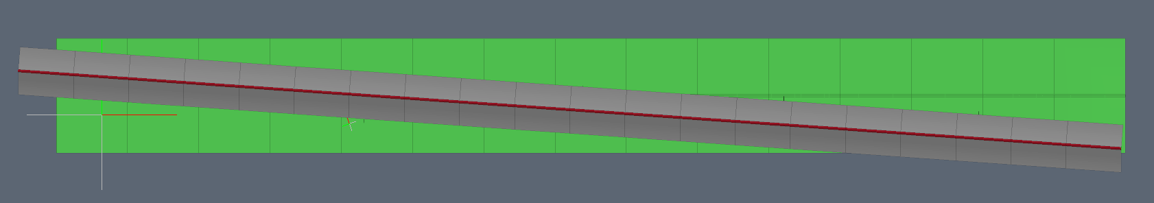
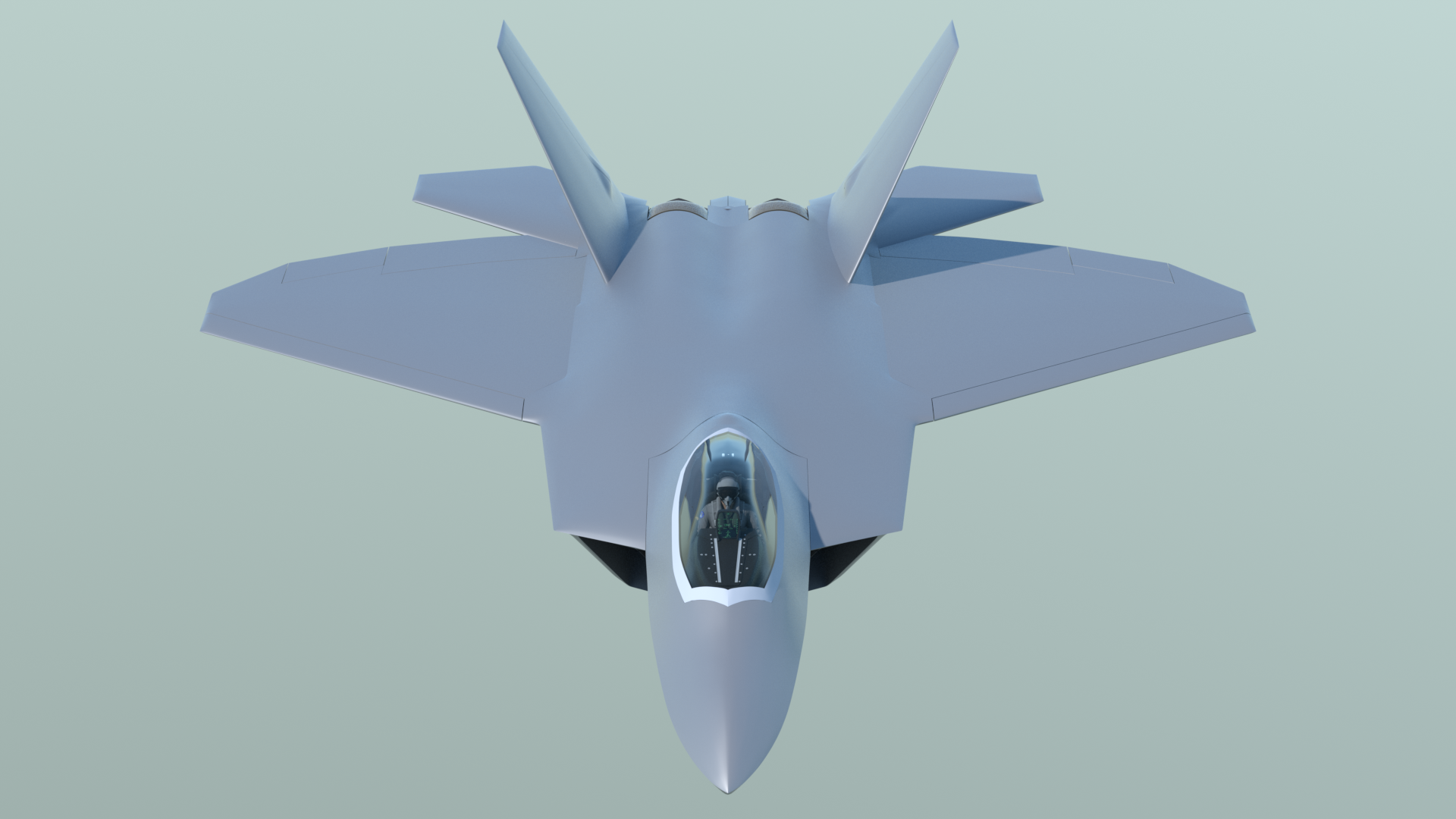
Viewed from the front, you can see how the guides help. Note that the guide in front (for the leading edge flap) is angled downward, and stays straight, although the trailing edge twists, due to the imposed washout.
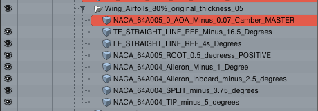
For those of you who are into the details, here's the exact rotational relationship I used for the five ribs. This is an educated guess, based on creating several iterations of the wing shapes, and comparing them to the orthographic Lockheed Martin drawings, as well as reference photos. It looks right, and matches the drawings, and is probably as close as I can get, without actual data from Lockheed Martin.
The wing was subdivided to produce a moderately-dense mesh, since their are other details to add, aside from the control surfaces. The basic problem with making control surface cutouts from a wing of this sort is that because of the taper, the polygons don’t produce a good polygon flow for them. So, I put the wings in regular hard-polygon mode, and used boolean cutters to cut out the control surfaces. The wing sections themselves were simply repaired around their edges as required, and edge-weighting was used to maintain their shape when placed back in Psubs mode. This went quickly, because I allowed a few triangles here and there, in flat areas.
The control surfaces were retopologized, using a very simple method. I first created a polygon for the top of each surface, by simply selecting one vertice at each of the four corners. I then cut that polygon and pasted it into a new mesh item, then subdivided it into about the same mesh density as the wings. This placed all the polygons in nice straight lines, and made maintaining quad polygons simple, Next, I used background constraint to push them up against the original surfaces, to produce their shape. The same procedure was followed for the bottom surface, and the two were joined. This worked great, and I used it for the leading edge flaps, trailing edge flaps, ailerons, and for the rudders. Once these surfaces were in place, it was simple to create the actuator bulges, using a proxy mesh item and background constraint. Here’s a video showing both processes.
There were several tools and methods that were used extensively to get the exterior geometry for this model into shape, and they are my favorites in MODO, for this kind of work:
- Background Constraint
- Edge Slide
- Action Center - Selection
- Smooth tool
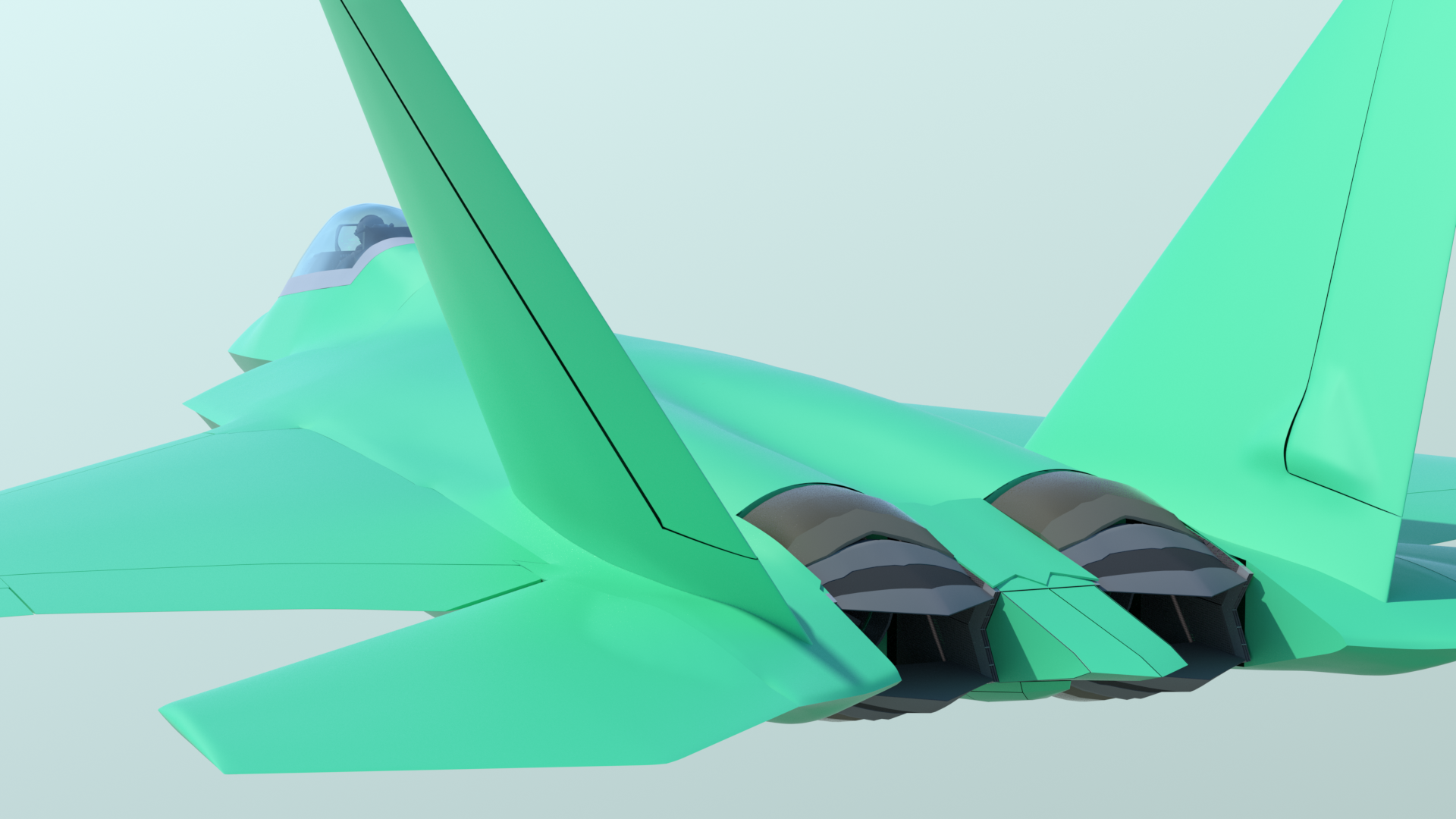
When I'm comparing shapes on the model to factory photos, I'll turn on the "primer" color, so that my images look similar. I've found this really helpful at times.
Priorities:
The fuselage shape blends into the wing and tailerons, (or “stabilators”, if you like) and so I felt that it was important to finalize their shapes before getting too involved with the fuselage. I carefully built the tailerons and the vertical fins, (using NACA 0009 airfoils thinned slightly) and cut out the rudders from the vertical fins. There are several reasons for doing this now.
Looking over some documents I found on the internet, it’s published that the taileron actuator pivot is 10 inches in diameter. So, using the Lockheed Martin drawings, along with factory photos, I was able to figure out where this pivot goes. That’s important, because there is a bulge in both the tailerons and the fuselage to accommodate that. The rudder cutout was important, because the base of the vertical fin and the rudders also have a similar bulge for their actuators, and this affects how those parts blend with the fuselage.
Finally, there is a detail about the taileron mounting that can be seen in both the Lockheed Martin drawings, as well as photos, if you know what you’re looking for. That is, the tailerons are mounted at a slight outward-canted angle. (I used 2 degrees.) The trailing edge of the wing’s inboard flaps also matched that angle. It’s subtle, but failing to notice that would mean that the fuselage, the fuselage/wing joint, and the flaps would be wrong. Details…
Overall Fuselage Shape:
As shown earlier, I separated the fuselage into the major components that I see in Lockheed Martin factory photos. This was handy for some initial planning. But, for getting the shape smooth, it would be helpful to have most of these parts in one mesh, so I combined them as shown, but used selection sets to keep them available for later separation.
When I first started this rebuild, this fuselage setup was essentially the same shape as my previous version, and I know there are some errors. So first, it was subdivided, to provide the ability to add more detail, and then many of the existing bulges for the actuators, gear doors, etc., were reduced or smoothed out entirely, so I could make the shape more accurate. All the prep time was again worth it, because what I’ve got so far is indeed more accurate to the actual aircraft. One of the main differences you may notice with the new model is that aft of where the main landing gear doors go, the bottom and sides of the lower fuselage taper upward much more than the original model.
The first step was to work on the taileron area, matching the fuselage shape to the actuator bulges in the tailerons. This was done using a proxy shape, along with background constraint.
I then worked my way forward, smoothing out the area where the vertical fins attach to the fuselage, and creating the “pinched” shape between the tailerons and the main wing, at the outboard edges of the fuselage.
From there, I moved forward, blending the outboard edges of the fuselage with the rest of the wings, and into the jet intake and canopy areas. Action Center/Selection was a huge help for this. Large polygonal areas could be initially smoothed with the scale tool, sharp edges, like the outboard edges of the jet intakes, could be straightened, and polygon selections were cleaned up using the Smooth tool, set to small values of about “20”.
There are some things that can’t be done with shortcuts. For example, doing a variety of selections and smoothing inevitably produces a little “lumpiness” in a dense mesh. So there were times when I turned on symmetry, went to Vertices mode, and got very close-up to the mesh, making very small corrections with the move tool, and using Edge Slide to adjust the polygon flow. Reflection mode is really useful for this, especially with the wireframe and vertices turned off. Obviously it’s also helpful to use a highly-reflective material, moving the main light around, and do some preview renders, in order to spot more areas to fix. I created a base material called “F22_Metal”, and used it for that. It also contains the blue-green ‘factory” color in the same group, so I can just turn it on and off, to compare the look of the model in different lighting situations.
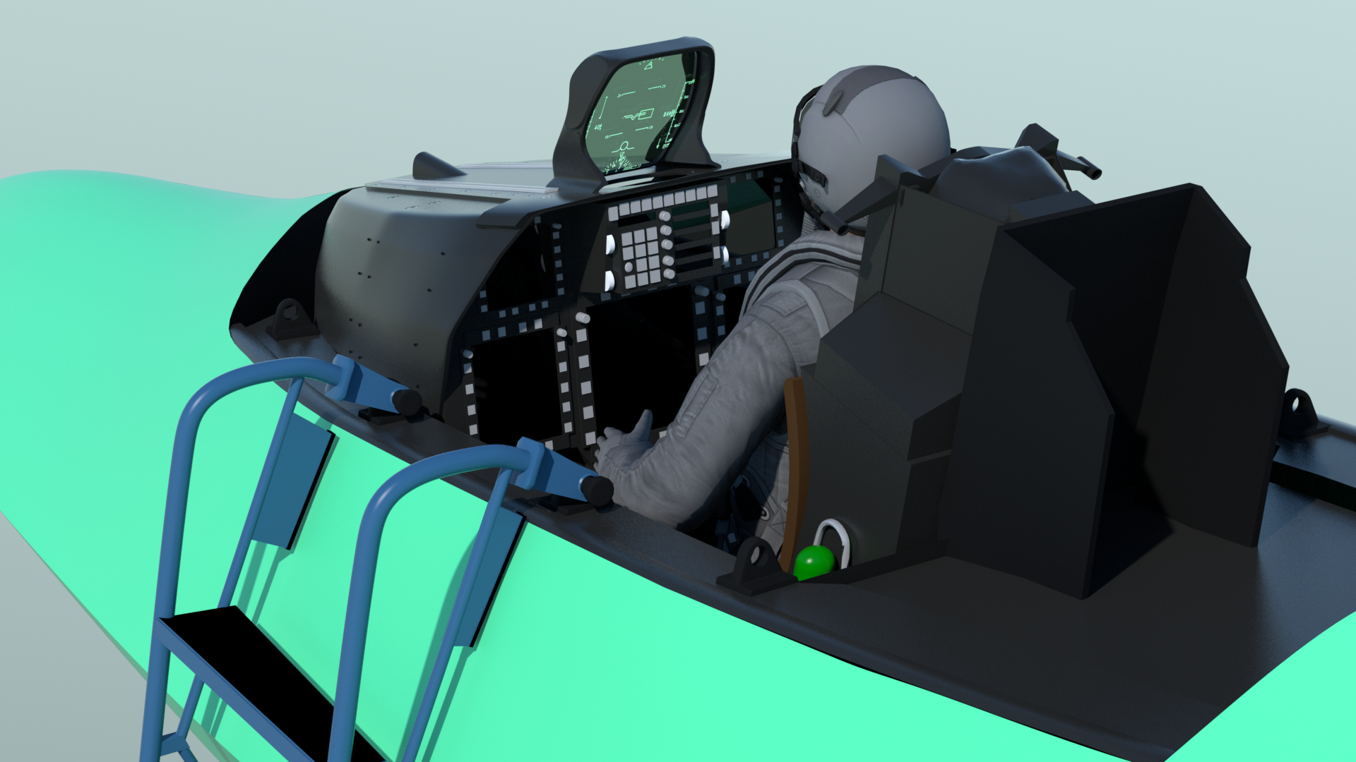
Some nice surprises:
There are parts of my previous model that are quite usable, which is a pleasant surprise. The exterior shape of the canopy and the canopy glass appear to be correct, and can be reused. Although the cockpit needs more detailing, quite a bit of it can be reused too. Bonus… I recently found a better jet pilot model (free) on the internet, which is more suitable for this model, and so I’ve roughly posed it to fit in the cockpit. I also separated it’s head, and attached a user channel to it, so I can turn the pilot’s head, as on the previous version. The rigging I had set up on the previous model, to open and close the canopy, still works, by copying it’s user channels into the new model, which saves me a lot of work. I’ll be improving the ejection seat, as I add additional cockpit detail.
It also seems that most of the landing gear can be reused, and only the gear doors themselves need to be rebuilt. (cut from the fuselage and wing parts, once that bulged area is created. It’s especially nice that I could simply copy the landing gear groups into the new model, along with their user channels, and the rigging still works.
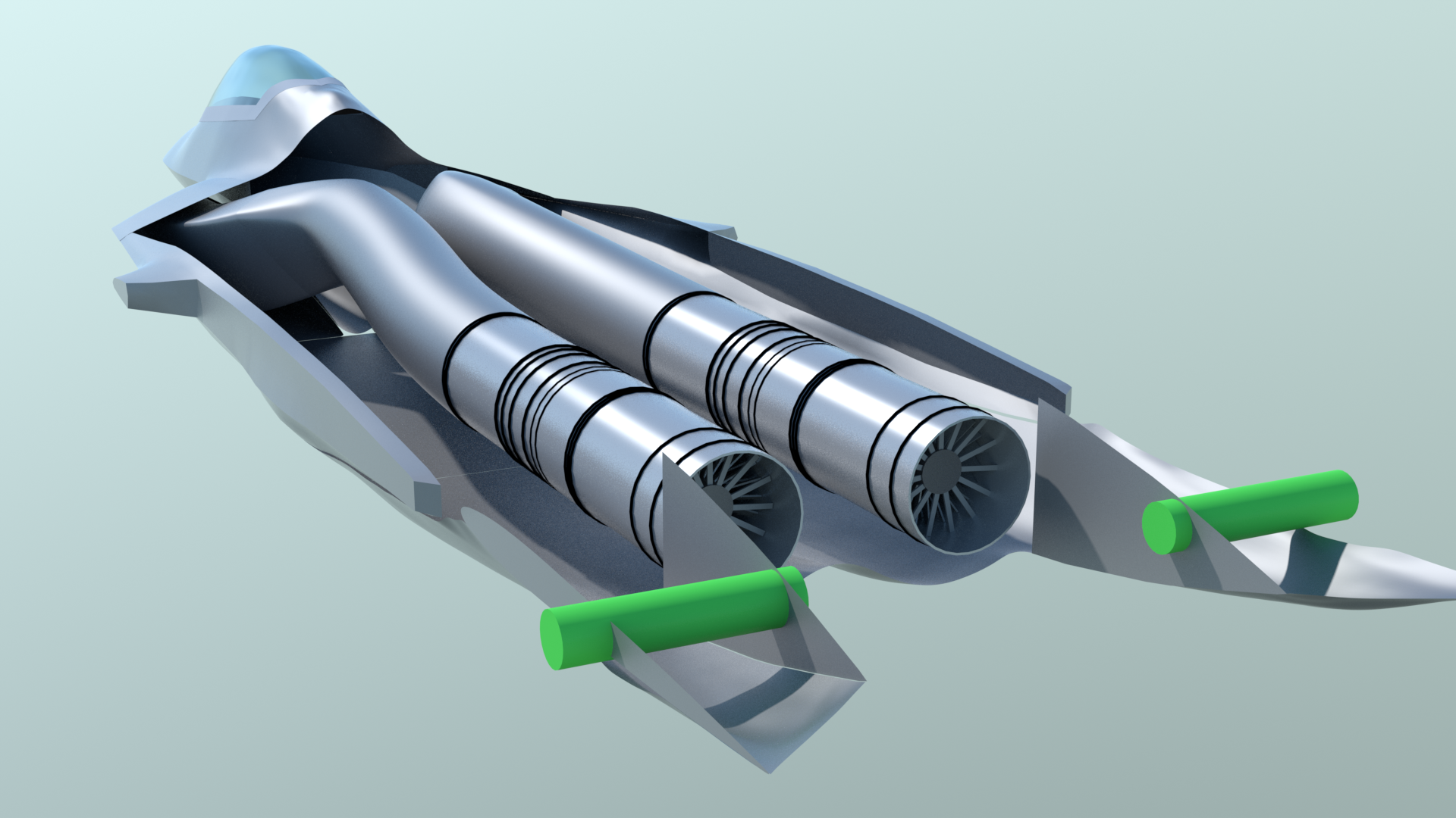
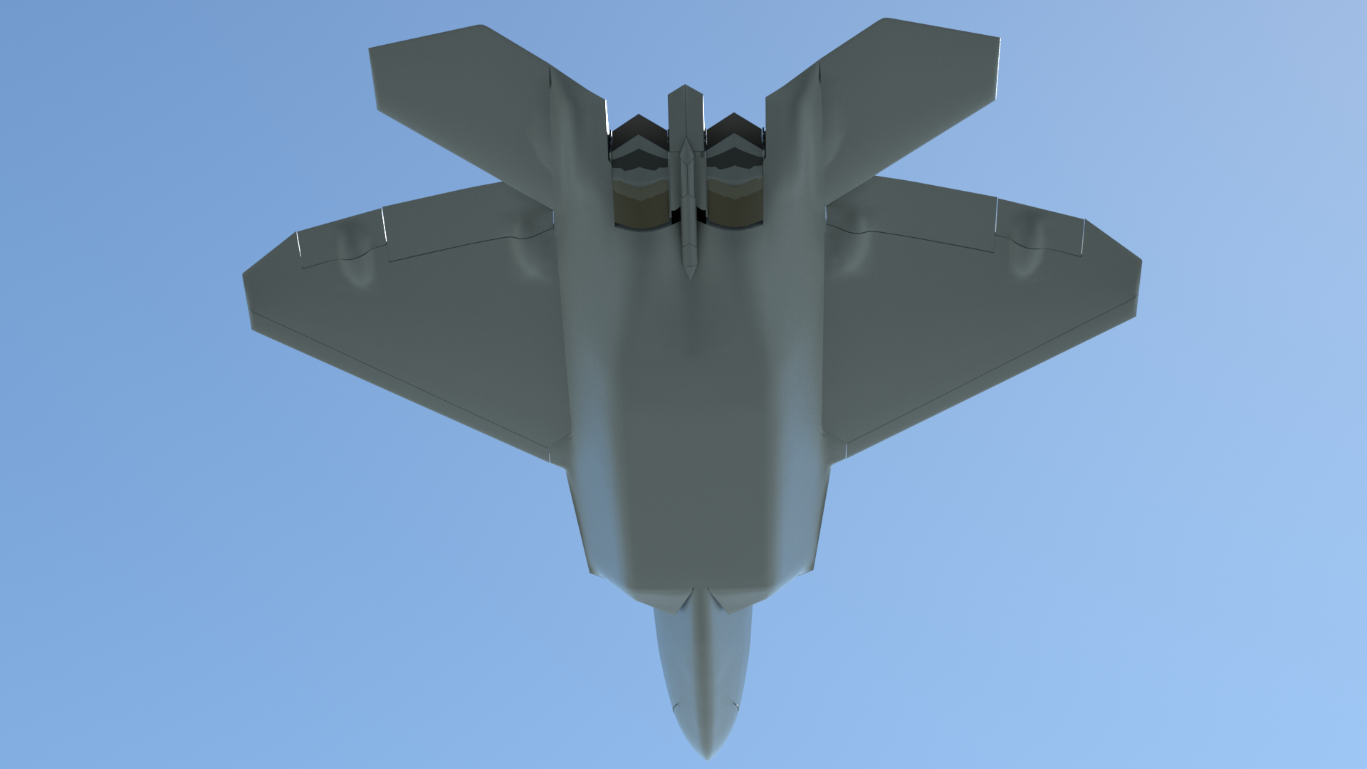
In reviewing my new documentation, I found another detail, which is that the intake ducts don’t have to completely diverge around the weapons bays, as I originally thought, The ducts do impinge slightly on both the side and bottom weapons bays, so I’ve adjusted both the ducts and the weapons bays accordingly.
I’ll be rebuilding the thrust-vectoring nozzles, but the ones from the previous model make acceptable stand-ins, until later.
What's next...
I’m going to spend a few days carefully reviewing what I’ve done so far, to be sure that the fuselage and other exterior shapes are squared away. Once I feel completely confident about that, the next step will be to create the bulges around where the main landing gear doors goes, Once that’s done, I can start adding the many sawtooth-edged panels, without worry that anything will be the wrong shape.
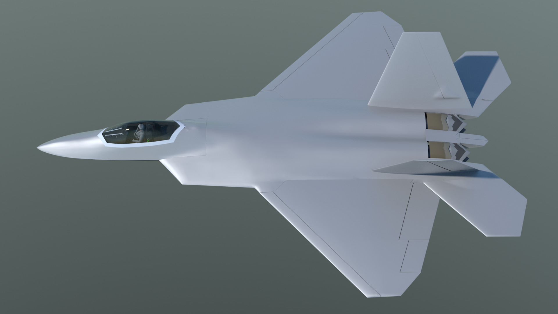
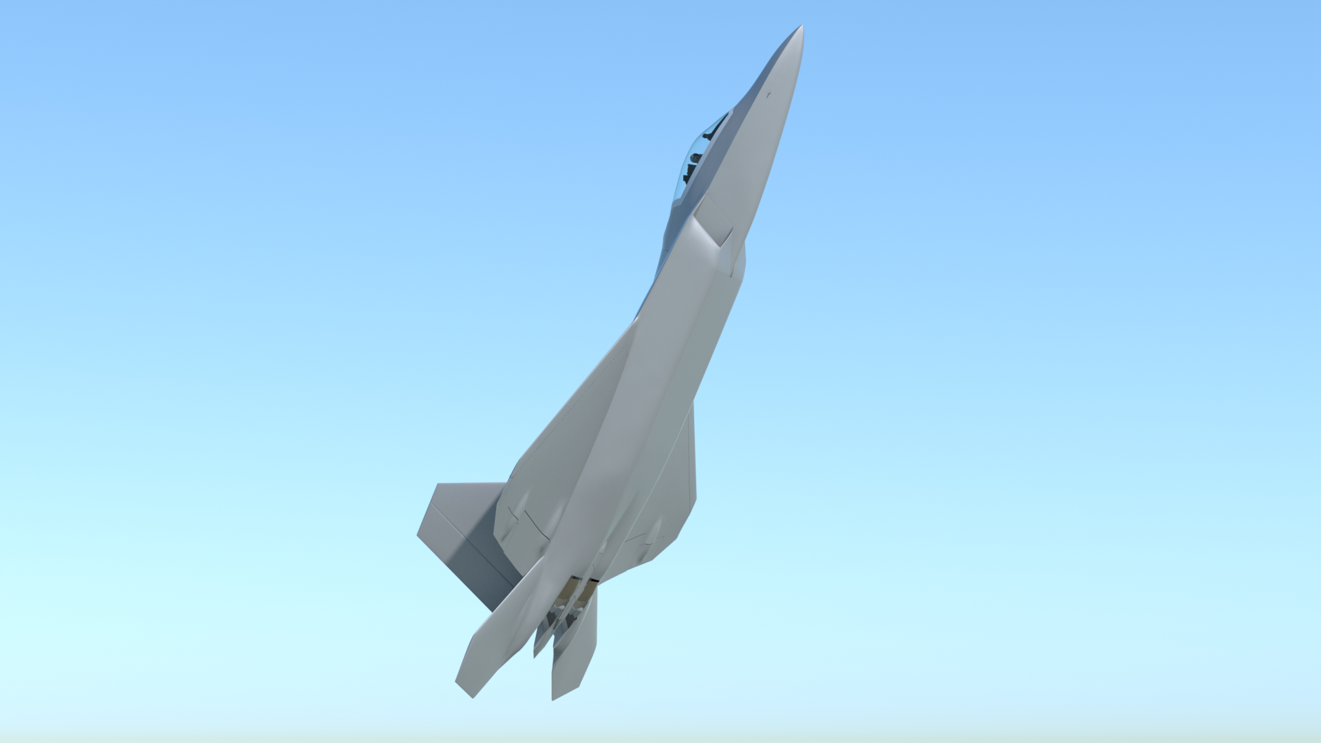
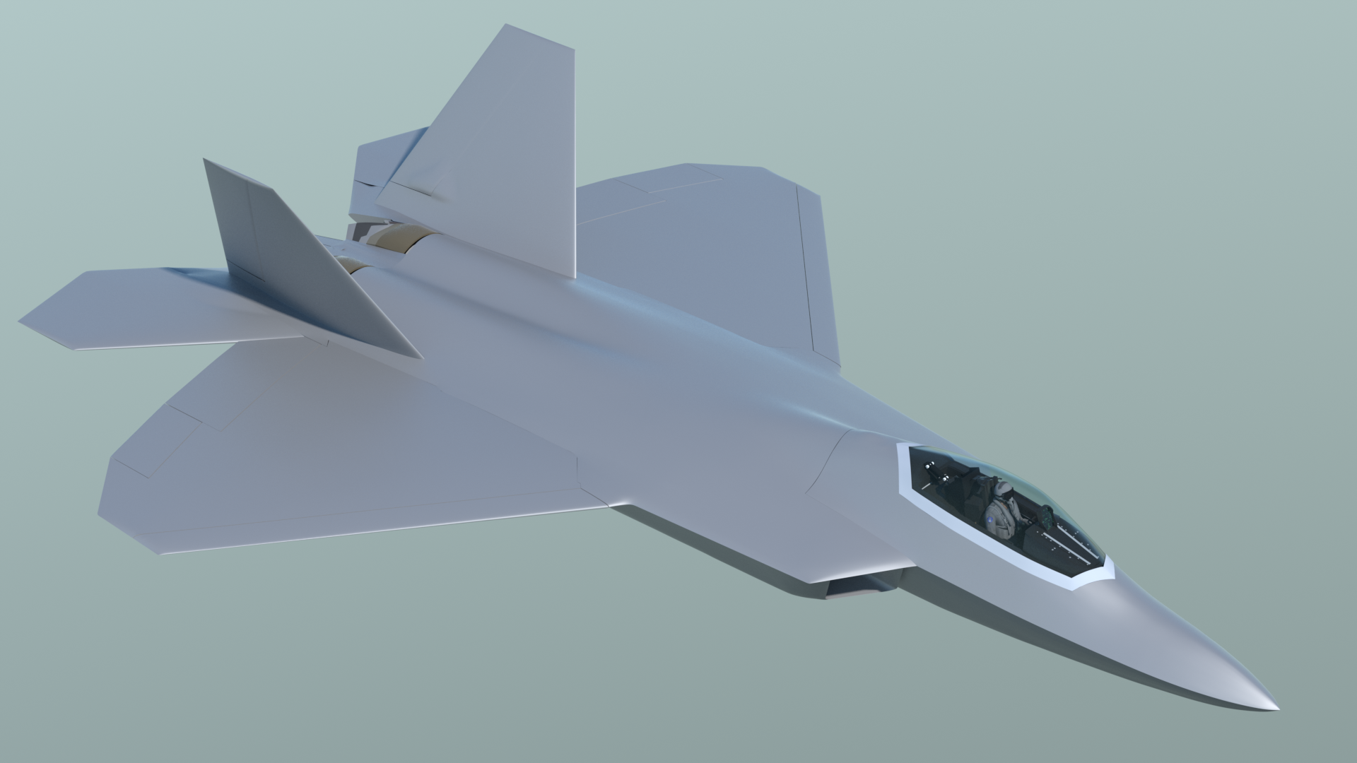
Update - January 13th, 2015: Here's a movie showing where the model stands as of today.
The exterior is getting very smooth now, and is nearly ready.
Click the "Page 05" link below, to continue.