NOTE: I am not at liberty to redistribute the documentation used to build this model.
This project is the focus of my tutorial set:
"Modeling with MODO, Volume Six - Building High Resolution Models with Catmull-Clark Subdivision Surfaces".
Piaggio "Avanti II" P180 Up-Res Project
 In 1996, I built a Piaggio P180 in Ray Dream Designer/Ray Dream Studio (predecessors to Carrara Studio) and it's been one of my most popular 3D models. After switching to The Foundry's "MODO" application in 2008, these much better tools allowed me to rebuild the model from scratch, with much more accuracy and much more detail.
In 2013, I began to receive more requests for two types of products. The first, was to export some of my models for the purpose of machining, both for creating display models, and for stereolithography. ("3D printing") The second type of request was to increase the resolution of my models, for the purpose of using them on larger displays and/or motion pictures. These two things, along with recent advances in both hardware and software, provides an opportunity which I'll explain below.
I'm also following the development of a new P180 variant called "Evo", and will include that as an option.
Click here for a brief preview movie, showing where this project is heading.
I have a LOT of time with this aircraft. Beginning back in 1995, I communicated with Piaggio engineers, built parts for a 1/6th scale physical version of the aircraft, and also built my first 3D model of the Avanti. I could not have done that without the tremendous communication I had with two engineers from Piaggio, Mr. Livio Cavini, and Mr. Paolo Chiarlone. In a kind of tribute to them, I've put together an article showing those things, which you can find below.
This is my third model of this aircraft done in MODO, as hardware, software, and documentation have improved over time. Once the current model got to the state where it is today, I removed the older articles from this site, to avoid confusion. For those of you who are interested in the original MODO model, you can view the whole thing in the reference article included with my "Modeling with MODO, Volume One" tutorial.
Why rebuild, and what will be different?
First, a big thanks to those who've assisted with the documentation...
As with the previous versions, this project was possible only due to the help of two fantastic people in Genova, Italy, who were engineers at Piaggio. When I built the original model, there was over a year of communication between Livio Cavini and Paolo Chiarlone, who provided me with outstanding documentation, as the basis for building a flying model at 1/6th scale. Find that story here. I want to also thank the wonderful people at Piaggio Aero., who provided further documentation. This model is now available in my 3D Catalog, and it will be continually updated.
This model will feature.... everything!
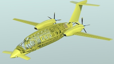
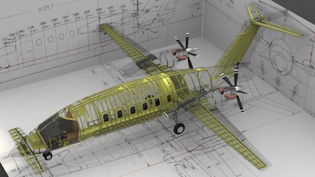
My previous P180 model showed some of the basic internal structures, including a few of the primary bulkheads, etc.. This version will include every piece of the structure that I can document, including ribs, spars, stringers, internal plumbing and wiring, etc., and will be my most advanced model to date. During the final phase, I'm also grouping all of that information into the same sort of assemblies used at the actual Piaggio factory, so that it can shown in a modular form. (i.e., the cockpit area, main cabin area, wing box assembly, etc.)
Up until 2013, I have typically built primary parts in sub-d, and then in cases where hatches and windows were required, I've frozen those parts to hard polygons, so that I could use boolean cutters. For protection against the future, I've generally built these models at a high enough resolution so that they could stand up to large monitors, large color prints, and many of these models have indeed been used in both advertising and motion pictures. This method has served me well for many years, mainly due to the time I've saved. Using boolean cutters on a hard-poly model is faster in many cases than creating equivalent parts in sub-d. This is still a perfectly good method for creating models with a lot of detail, in a big hurry, and especially true if the goal is rendering and animation, rather than something that demands a certain type of polygons.
But... Technology always improves, and any model with a fixed polygon size has a limited shelf life. I've also found that sub-d models have more potential for export to other file formats, including those used for machining. Modeling in "Psubs" (Catmull-Clark subdivision surfaces) provides the ability to increase the resolution at any time by increasing the subdivision level. So, it's time to increase the resolution of my models, and I expect to use that approach for most of them.
There are of course, challenges with that method... creating all the fine details such as windows, hatches, and doors in a sub-d surface while minimizing smoothing errors is the biggest one. This exercise has been a great and ongoing learning experience, and I'll be sharing what I've learned here.
And finally...
Knowing that MeshFusion was designed to use with Catmull-Clark surfaces influenced my decision to model this way. In my opinion, this tool set will change the way we work, in some revolutionary ways.
Starting with a clean slate
A quick note on aircraft documentation...
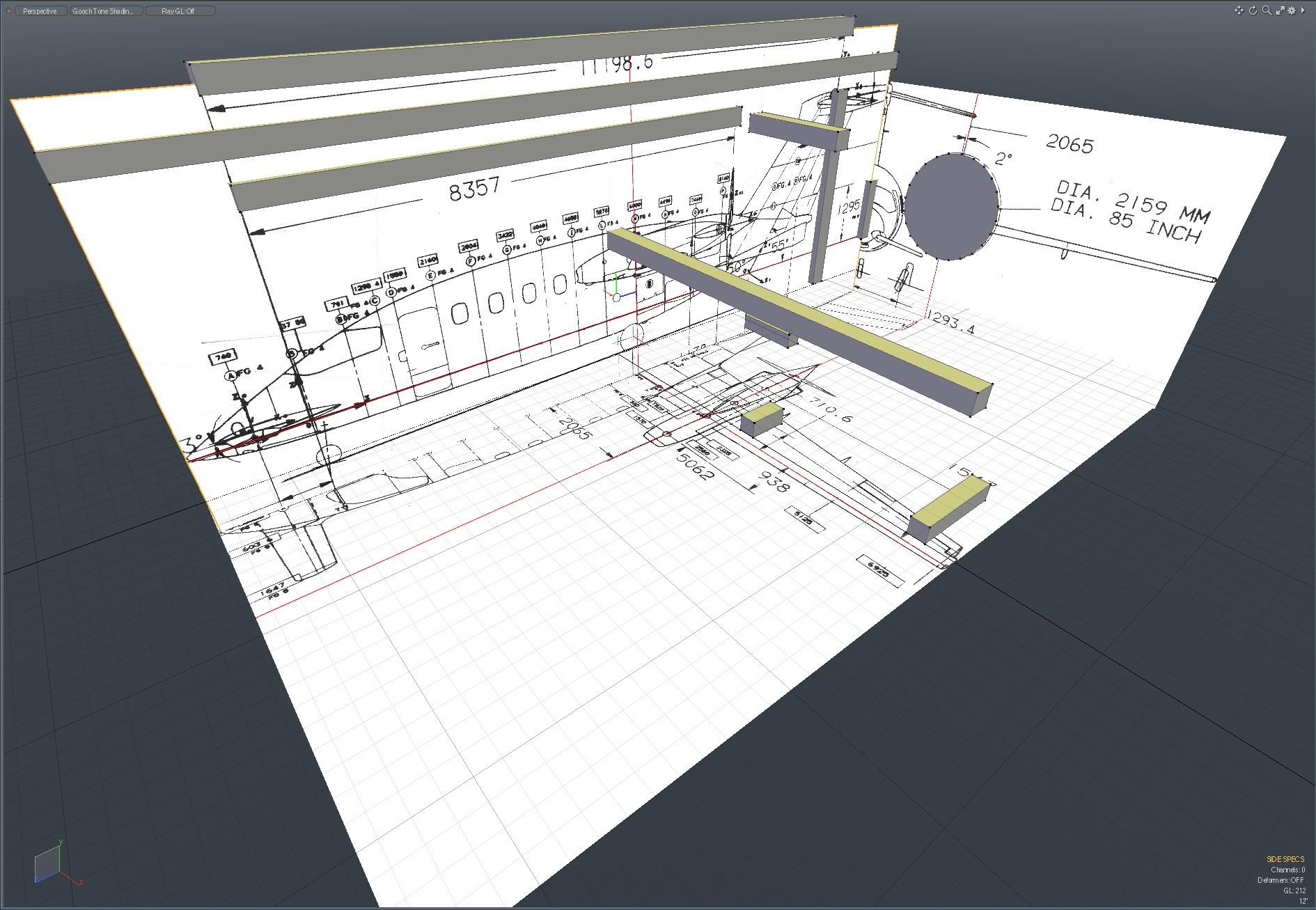
Aircraft manufacturers don't have a need for the kind of drawings that we want as 3D modelers. In the case of older aircraft, the original tooling was developed from gigantic drawings of individual parts and sub-assemblies. Today, most manufacturers (Piaggio included) are using "Catia" to design and update their aircraft, and they certainly don't have a need to produce "3-views and cross-sections". So, when you find these, or even if you obtain them from the manufacturer, realize that they were probably done for a wind tunnel model (That's the source of my P180 drawings.) or for the purpose of planning a display model. They're not going to be "real" drawings used in manufacturing, and so you must extrapolate some details for yourself. Simply put, there are no perfect drawings in existence.
Until this model is finished, I'll be keeping some of my previous model's parts in the same file, for reference, and for use in some renders. But, this model is completely new, and every part will be replaced, as the project continues. So, once again, I carefully checked all of my documentation and it's placement in MODO, I then created a variety of "rulers" within MODO, to check the real-world size of know measurements against the drawings. No modeling was done until I was completely satisfied that the references were correct and in the right place.
Important prerequisites for this kind of modeling
This model is intended to be an accurate representation of the actual aircraft, and so my methods are oriented toward creating parts that can be separated as they are on the actual aircraft, rather than just creating the overall shapes. Knowing that will explain why things were done in certain ways. For example, when I create the wing parts, I don't just want to create the external shape. Instead, I will create the initial model so that the skin can be separated into the same sort of parts as on the actual aircraft, and I'll plan the spacing of the edge loops so that those loops identify where internal ribs go, etc..
The "purity" or "cleanliness" of a sub-d mesh is subjective, from a rendering point of view. In other words, if the mesh renders beautifully, it's completely irrelevant if it happens to have polygons in it that are not triangles or quad polygons. But, if you intend to export the mesh to other file formats (or if your work pipeline demands it for some other reason) then maintaining your mesh is important. This model is well over 99 percent quad polygons, with a few triangles here and there, where it was helpful.
Every 3D modeler knows that you can often create convincing complex shapes by combining several simpler primitive shapes, and allowing them to intersect. In this case, we're going to be showing the interior of the aircraft, including it's structures, etc., so this won't work. We need to actually build these complex shapes (like the engine nacelles, for example) correctly. More work, but also more rewarding at the end.
When additional edges and geometric detail are added to a sub-d model, smoothing errors can easily develop, and if you're in a hurry, they aren't always obvious. For example, the use of a flat display material, like MODO's "Gooch Tone" choice, can hide some of these, and in renders, the use of Global Illumination can hide many such defects. It's important to know that, so that you don't spend a lot of time modeling, only to find later that your model is a mess.
So, I work a great deal with the "Reflection" material in the modeling viewport, and frequently turn the wireframe off, to see smoothing errors that can be hidden by them. I always preview the model in the renderer with Global Illumination turned off, and I use a highly-reflective surface on the model during construction, so that in Preview, or a render, any smoothing errors show up. Remember that a "glass" or otherwise-transparent material can also hide smoothing errors, so check those parts with another material before committing to transparency. If the model looks good under those circumstances, then you know that any other viewing method can only look better. Going slowly and carefully, and saving multiple copies of your work is always a good idea.
Modeling tips for this kind of work within MODO:
There are several things we can do during the modeling process to keep surfaces smooth where they need to be. This is made much easier by a great tool set, and MODO has some of the best modeling tools for this sort of work.
 The most important step in sub-d modeling is the careful planning of edge loop placement, which is dependent on what you intend to do with the model. For example, in organic character modeling, it's important to create proper edge loop "flows" around critical areas that will be animated or deformed. We do that so that the animation can be done on one part of the model without negatively affecting another part, and also to avoid "kinking" and "bulging" in unwanted places. With a hard-surface object, such as an aircraft, we do this to allow parts to be separated for animation and other purposes, while maintaining the desired (usually straight) seam lines. So, a plan is in order. For example, will the model include visible (and possibly separable) seams? What parts will be animated? What can we do to maintain the overall smoothness of the surfaces, while allowing these separable and animatable parts? Scale has something to do with your decisions, too. In other words, a "close-up" may mean one thing if you're modeling an aircraft like this one, and quite another thing if you're modeling a Boeing 747. Give some thought to how you intend for the model to be rendered, (or to how others may render it) and then at a higher level than that, to be sure.
Of course, we can't create all of these seams at once. In fact, it's often unwise to try. As one example, let's say that we're going to detail an aircraft's rudder. It makes more sense to develop the primary separation lines, cut and paste the rudder mesh into a separate item, and then do those mods. That way, whatever you do to the rudder won't affect the topology of the vertical fin you cut it from. This kind of thing happens a lot during the construction of a model such as this, and it often pays to simply stop and think for a while, before taking the next step. And ALWAYS keep at least one backup of the previous version, so you can recover if you get in trouble. Looking at the computer keyboards I've owned over the years, the first key to have the ink start to fade from wear is always the "S" key. There's a reason for that! I always keep several incremental backups on my computer, and (on a Mac) use "Time Machine" to create backups automatically on an external drive. So, I have versions from the start of the project if I need to backtrack, and this has saved me more than once. I'm such a file-safety fanatic that I also keep especially-important files backed up on a remote server, and even on some iPods and thumb drives, too. You never know...
You'll need to work on parts with sub-d turned off and on. If you find yourself having to move parts into really strange positions, in hard-poly mode, to get the shape the way you want it in sub-d mode, this is often a sign that you don't have enough polygons. Even when in it's hard-poly mode, your model should have a reasonable shape and polygon flow, and ensuring that it does will make it easier to edit in the future, too. In MODO, remember that the TAB key places you in MODO's default sub-d mode, but you need to use SHIFT-TAB to go into "Psubs", or Catmull-Clark mode. Again, the Lists tab in the Properties window comes into play, if you can't tell which mode you're in, visually. These two types of subdivision surfaces react differently, so it's important to keep track of the mode you're in.
For me, several of the greatest tools within MODO are "Edge Slide", (which also works with individual vertices) "Background Constraint", (a HUGE one!) and "Loop Slice". (with the "Preserve Curvature" option turned on. Falloffs are a spectacular tool, too, not only for modeling, but for correcting errors later. When you have a difficult-to-edit assembly of parts, sometimes you can edit the whole group at once, using a falloff. You'll see me use these over and over during this kind of a modeling project, and I'll cover these in much more detail in "Modeling with MODO, Volume Six - Building High Resolution Models with Catmull-Clark Subdivision Surfaces". To keep this article a somewhat reasonable length, I'll mostly just show the results here, with brief remarks about the "how".
Another simple, yet effective tip for building this sort of model is simply the idea of hanging on to many of the initial parts until the end of the project. For example, when I first built the vertical fin, I used known airfoil cross sections, and built it in one smooth piece. Before cutting away the rudder, and detailing the separate parts, I made sure to keep this original. Later, I'll want to add internal ribs and other formers to the tail parts. Having a copy of the original one-piece structure allows me to form many of those in one step, by either slicing up a copy of it, or by using the interior of that shape as a background constraint. That's much easier than trying to first create formers in the vertical fin, then creating separate formers in the rudder, and keeping them all aligned. So, standard procedure for me is to keep a folder of "Originals and Cutters" at the top of my model's hierarchy until the project is finished. Even then, I'll remove that from the final file, but keep it backed up separately. That's insurance, should I need to go back and correct or update something later.
99% Catmull-Clark, no nGons, no replicators, no instances, and no edge-weighting. Why?
Specifically...
There are no nGons in the model, and only a very few, tiny triangles. There is no edge-weighting used in this version of the model, and there are no instances or replicators, so that I could export it accurately to other file formats. There are a very few bits of geometry that are hard polygons. (i.e., some of the wing and fuselage stringers, because sub-d was not necessary, and adding the extra edges would've been a waste of geometry, for no benefit)
There's another reason I chose this method. That is, I'm also rebuilding my F-22 "Raptor" model, and have chosen to built it using Catmull-Clark (Psubs) surfaces on that one, but with edge-weighting, rather than additional edge loops. These two models will show that either method can work equally well, and the advantages/disadvantages of both. That article begins here.
Exporting to other file formats:
The decision to use Catmull-Clark surfaces for this project means that in its original form, the model's resolution can be increased in the future if needed, by simply increasing the subdivision level. If you find yourself needing to export to hard polygons, that's still important, since you can up-res the model before converting it.
Over the course of a model like this, many parts will be duplicated, especially things like screws, rivets, and toggle switches. Within MODO, the use of instances and replicators can save you a lot of time, make editing of "master" parts easy, and can also reduce your file size. But, you have to consider whether the model is intended for export to other file formats or not. If it is, then it may be worth the increase in file size to use actual geometry. You're "safe" either way, since you can always go back to the original file and convert your instances and replicators to actual geometry, but you have to be careful if these things are animated.
Some things simply cannot be overcome. For example, the animation channels and their controllers simply will not universally transfer to all other file formats. So do what you can to make your file "universal", but use tools that enhance the original model, regardless.
This is not a race.
There's no place for "speed modeling" in a project like this. It's intentionally designed to be viewed and rendered up close, so we're not trying to take lots of shortcuts to create a distant, "ok" render. Certain concepts still apply, like not modeling parts that will never be seen. (i.e. the threads on a screw that is hidden within the structure) Otherwise, I'm building every part with a great deal of care. Of course, with careful backups in place, you can do anything you like, and remain safe, by simply reverting to a backup. But... You'll save time in the long run by moving slowly and carefully. I'd rather spend 30 minutes building a simple but "perfect" part I can freely use over and over, rather than building it sloppily, and later having copies of it scattered across the model. In MODO, it pays to use "Mesh Cleanup" and "Merge Vertices" often, so you're not surprised later with screwy geometry. Remember to also check the "Lists" tab in the Properties view, to keep an eye out for Ngons, stray vertices, and different polygon types.
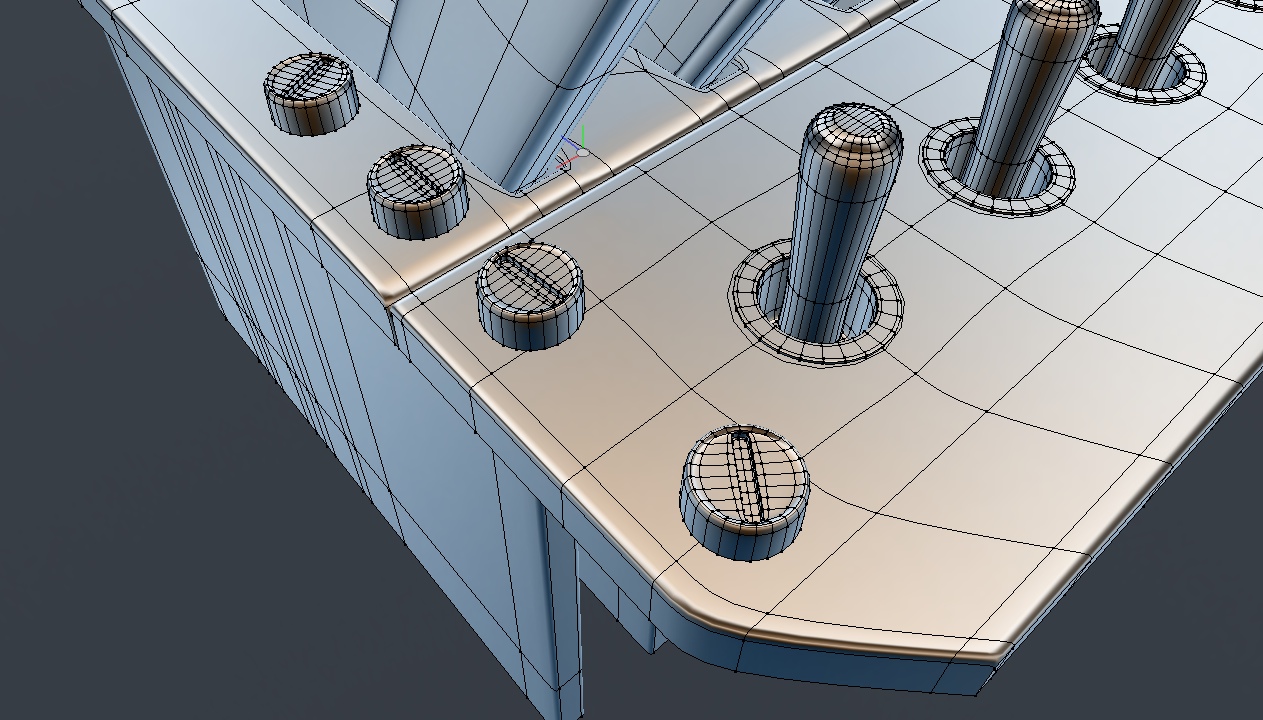
Think about something like screws, in a model like this. There are a LOT of them especially-visible in the cockpit, on the instrument panel. As you place these, it's worth taking the time to rotate each one slightly (somewhat randomly) to that all the driver slots are not aligned the same. This small step adds realism, and it's easier to do that as you place them, rather than waiting until you have several hundred of them in position.
In general, you have to be willing to do several things to create a project like this. First, realize that there will be a lot of repetition of "procedures", such as the screws mentioned above. Second, to get some details right, you must be willing to sometimes spend hours pushing individual edges and vertices around. And finally, you must be willing to start over on certain parts of the project when you've screwed up. It's bound to happen on a project like this, (I'll provide some examples) so don't let it get you down.
On with the modeling!
Click the "Page 02" link below, to continue.