NOTE: I am not at liberty to redistribute the documentation used to build this model.
2015 F-22 "Raptor" High Resolution Project
"Tricks":
"Tricks":
From an engineering point of view, you have to admire the success of Lockheed Martin in disguising the actual shape of the F-22. Having studied hundreds of photos of this aircraft, and having been mislead many times, here's just one example...
Here are three different view of the gun port area on the F-22 fuselage. I believe these are in chronological order. Notice that the gun port area in the first photo appears to have 3 distinct shapes... a depression at the front, followed by an outward bulge at it's rear, and then another bulge upward, a little further aft.
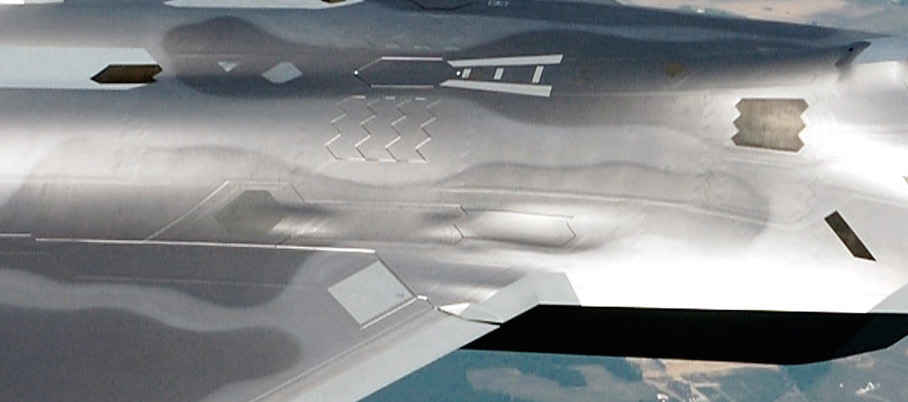
This second image looks like the surface has the same shapes as the first, but they look much more subtle.
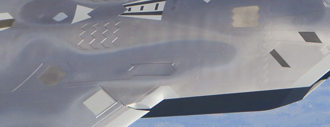
This image, which is definitely the latest one, shows an even more subtle shape.
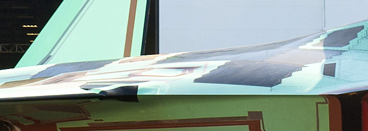
There's no definite conclusion to be drawn here. One possibility is that these are F-22s manufactured from different "blocks", and that they've modified the shape over time. Another possibility is that the paint on the aircraft in the top photo simply exaggerates the look of those shapes. My decisions on this current model will be made on what I believe is the most recent documentation, and so I will, for example, reduce the exaggeration of this gun port shape that appears on my earlier models. There are literally hundreds of places around the aircraft where these shapes are confusing visually, and I'm sure that's exactly how Lockheed Martin wants it. Frustrating to me, but successful for them...
I don't know any more about this aircraft than any other civilian could discover, given the same amount of research and effort. There are of course no "military secrets' here, or anywhere else on my site.
Planning cuts and panel lines
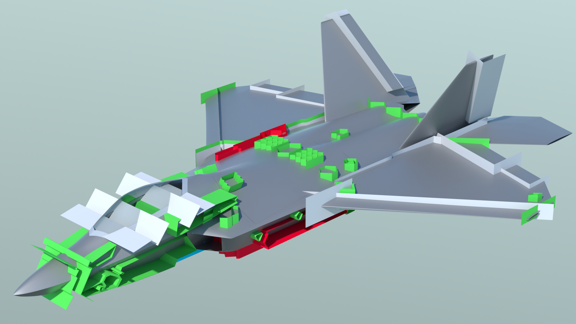
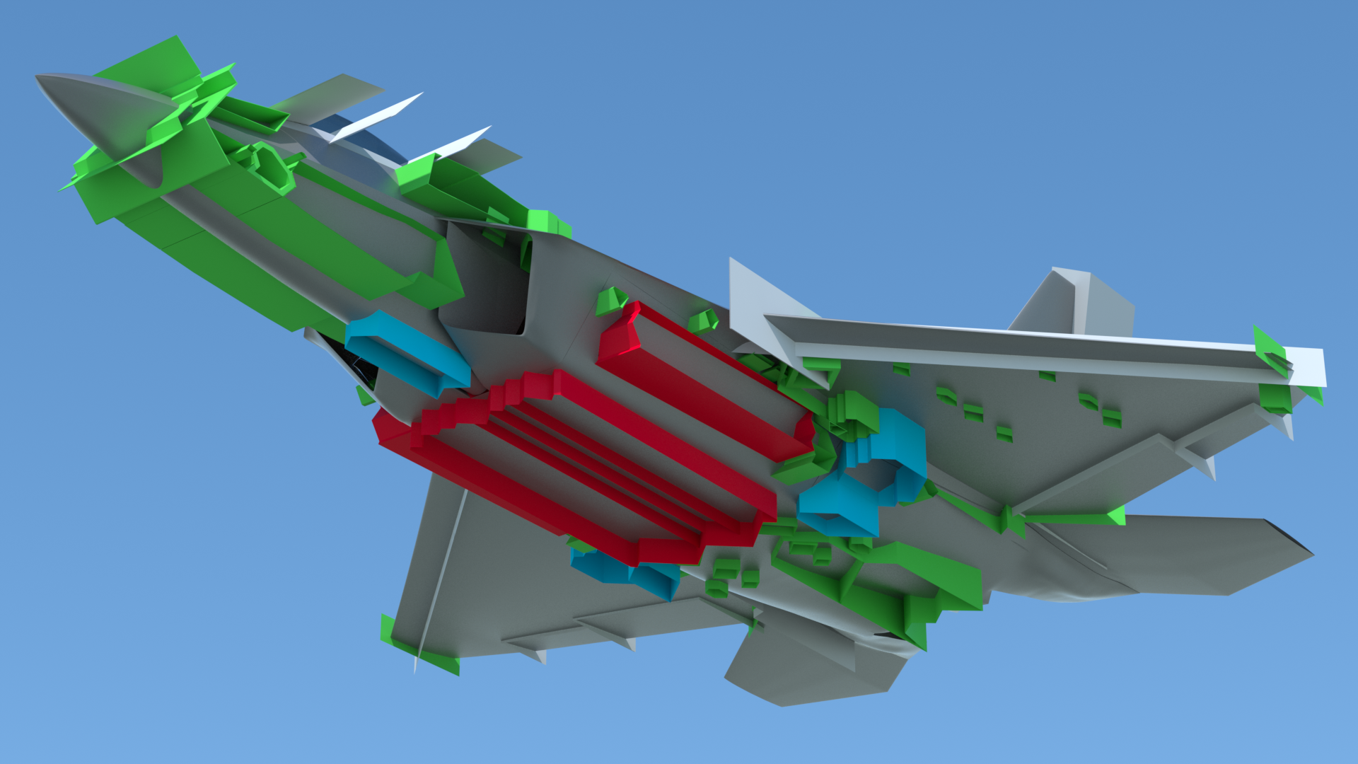
I always save everything that I think might need to be used or adjusted in the future. In the case of the F-22, I’ve saved all the items from previous versions that were used as boolean cutters. Now, these will be used to define both cuts and panel shapes on the Psubs version.
The white-colored items are used to define where cuts will be made for the control surfaces, and where some panel lines occur on the canopy frame.
The red-colored items define weapons-related panels. (gun port on the fuselage top, and weapons bay doors on the sides and bottom of the fuselage.)
The light blue-colored items on the bottom of the model indicate the landing gear doors.
The green-colored items are for the various panels I’ve identified so far. (the trademark stealth-related, zigzag-bordered ones) There are many more of these to be added, and that’s what I’m working on at the moment. Since these aren’t going to be used as “cutters” this time, they’ll be converted from edge-based shapes to polygon-based shapes. Then, I’ll background-constrain them to the part they belong on, delete the underlying polygons, and stitch them into the geometry, as I did with the sample panel test I showed here previously.
Here’s my “extrapolation plan”, done with the aid of various cutaway views available on the net.
The panels (green-colored parts) are there for a reason, which is typically to define an access area for something below, or to act as an intake or vent from something below. That in turn will tell me where there’s space for a structural former. So, exterior panels first, followed by building the internal items related to it, then structural formers later, once I know where they go, and what holes need to be in them, for ducts, actuators, plumbing, etc..
Click the "Page 04" link below, to continue.