NOTE: I am not at liberty to redistribute the documentation used to build this model.
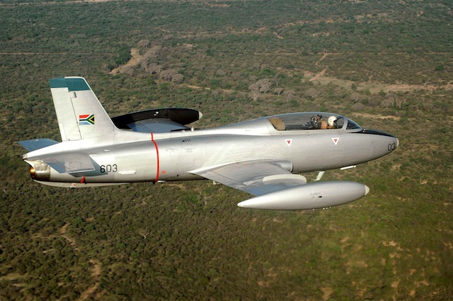
Aermacchi MB 326G Project
 Quoting from Wikipedia:
About this project, specifically:
This 3D model and it's renderings are being developed to aid in the fabrication of a large, turbine-powered, flying scale model intended for a World competition. So, in addition to modeling the aircraft to scale, there will be considerations made for physical fabrication. (removable wings, etc.) I've included a rather in-depth discussion of the whole process in my latest MODO training tutorial, "Modeling with MODO, Volume Five - Problem Solving".
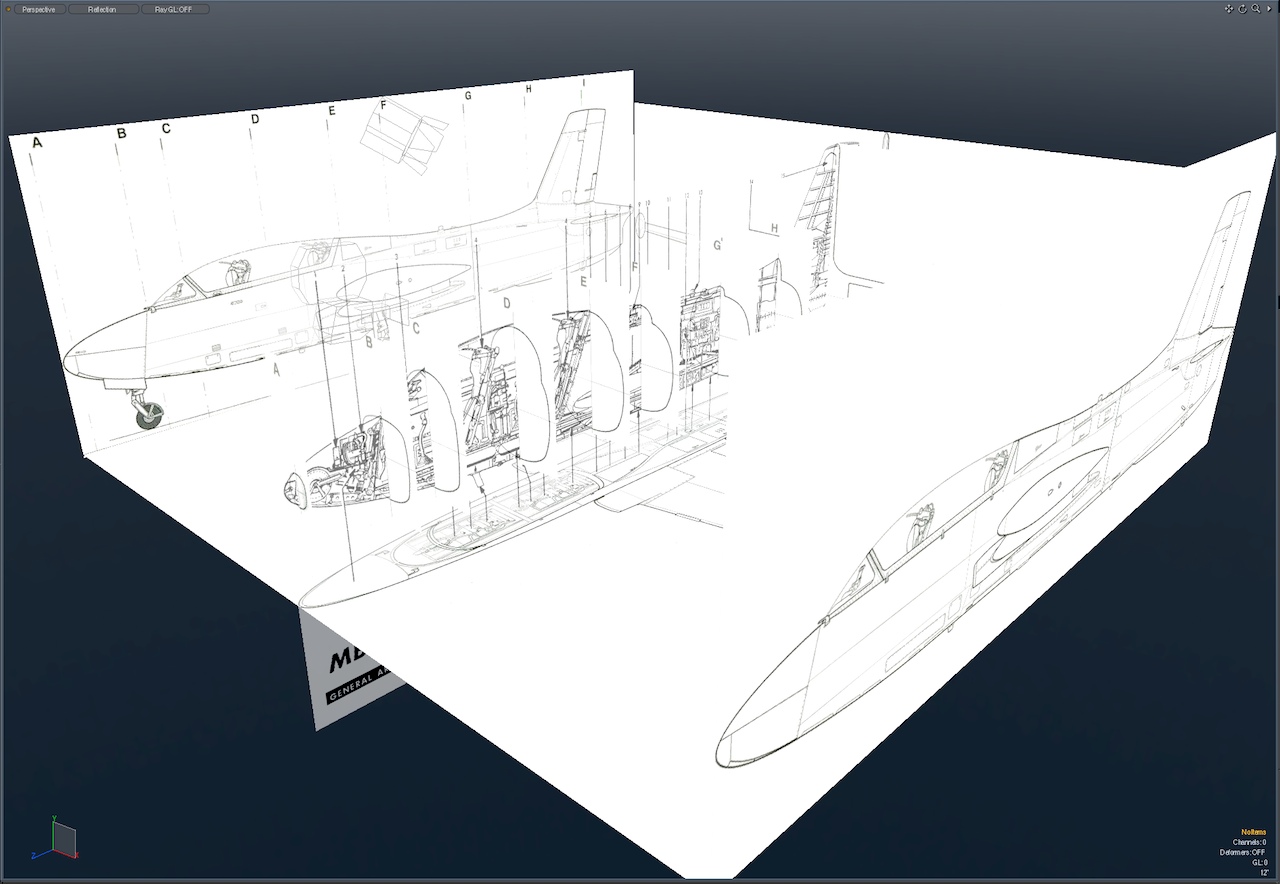
As usual, we start with the documentation..
First, a warning for those who would attempt to copy this design...
Note that the drawings shown in this article are NOT the ones used for the actual model. This is for the protection of the customer, so they keep their competitive edge. There are only a very few orthographic images shown anywhere in the article, and they're all on this first page. So, be warned that copying anything shown here would be futile and inaccurate.
After choosing a set of drawings that we believe to be accurate, those were sliced up and scaled in Photoshop, so that they could be used as backdrop items in MODO. It's important to check at this stage, to be sure all the drawings match each other, and in this case, they do.
The next step was to verify the shape and position of the wing and tail airfoils, so they could be blended with the fuselage properly. Here are the steps:
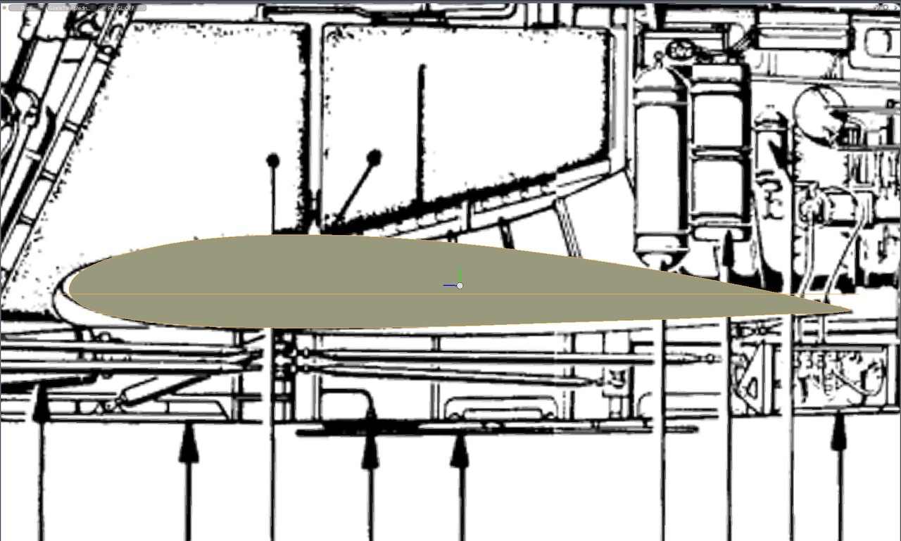
First, we located an accurate plot of the (NACA 2412) airfoil to be used, and recreated it in MODO. (Later, we changed to a different airfoil.)
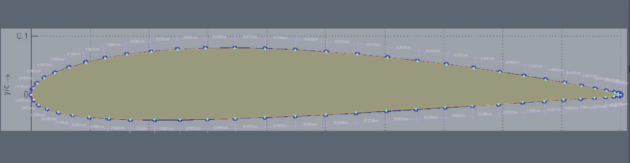
(Smoothed in sub-d mode)
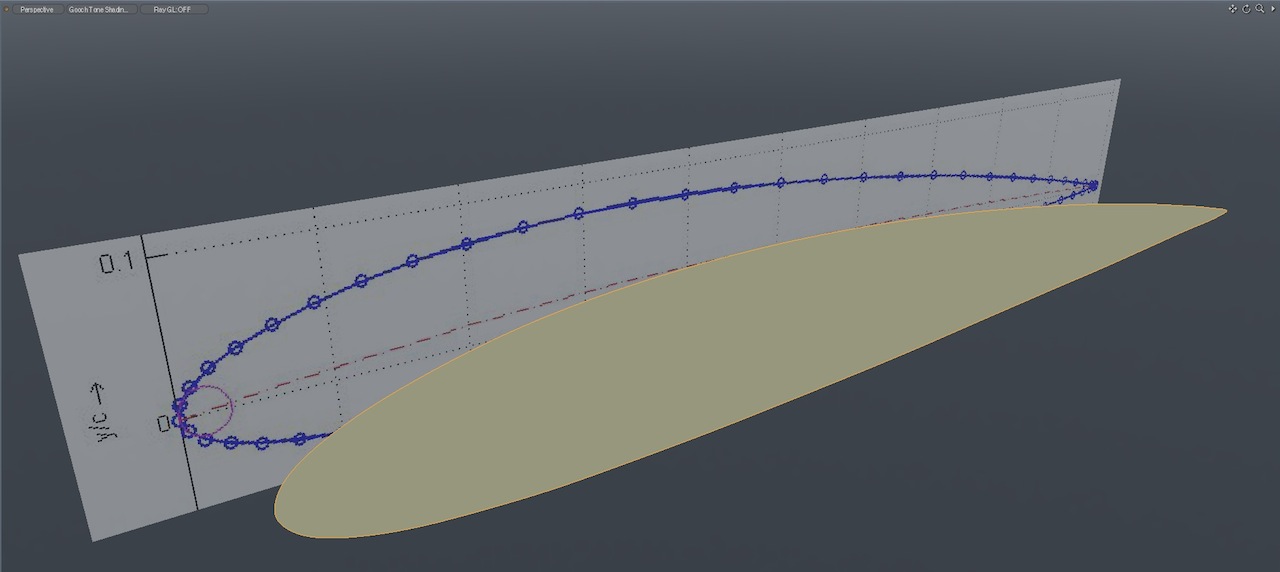
A proxy shape, representing the top-view outline of the wing was created, to determine the chord (length in Z axis) of the root and tip airfoils. (the light orange lines shown here, over the reference drawing)
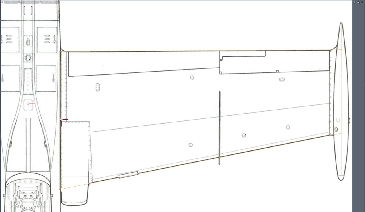
Finally, the airfoil shape was rotated to it's correct angle of attack, to match two different drawings we had, as closely as possible.
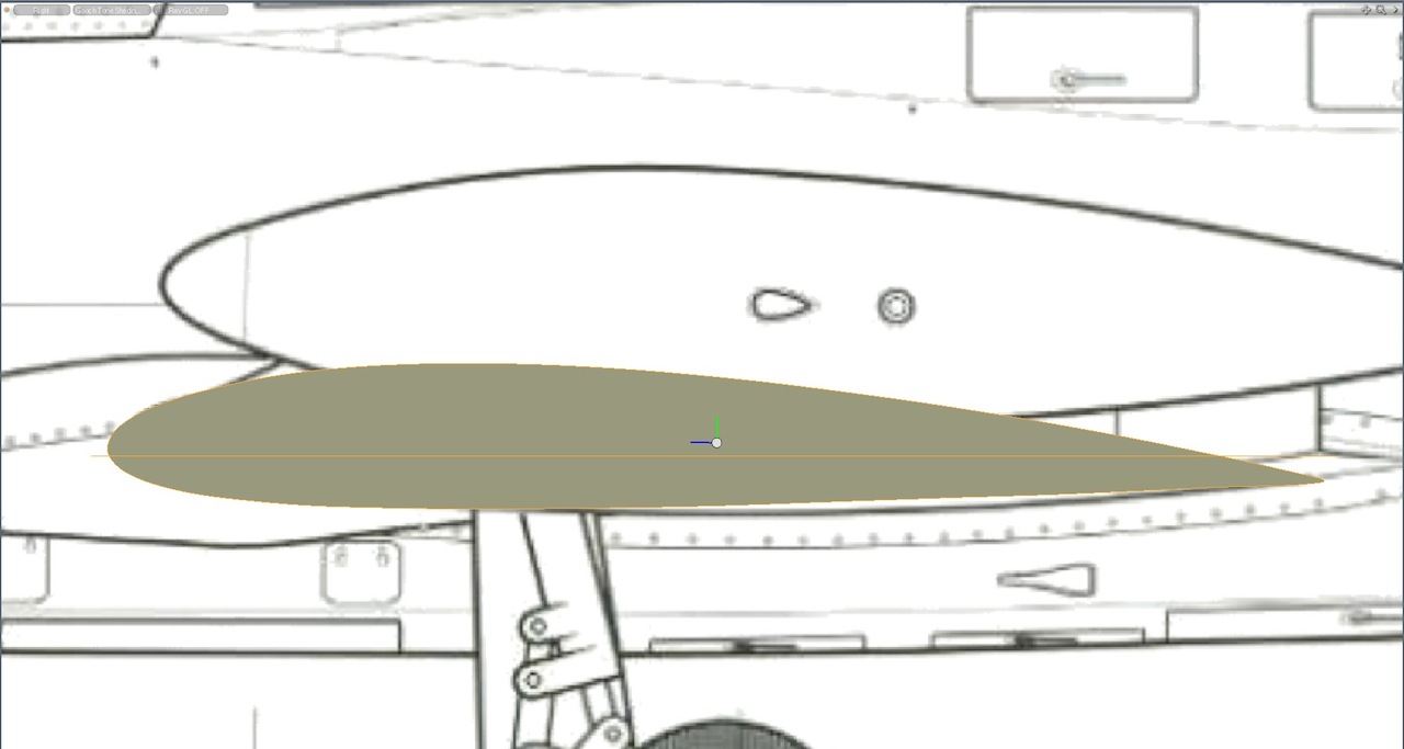
None of our drawings shows the exact position of the root airfoil, but some simple logic helps prove we're right.
- Knowing that the aerodynamic zero of this airfoil was probably at about 1.5 degrees, and that the decalage should be the same amount, and knowing that it's often common practice to have the horizontal stabilizer at zero degrees, (with a symmetrical airfoil like the one we're using) it seems obvious that the wing should be mounted at 1.5 degrees positive aoa.
- We can reasonably test that by rotating the wing root profile to that angle, and comparing it to both our main drawings, and the cutaway view. We can see that it nearly matches. (Neither of those drawing shows it exactly, but it's pretty close, and the reasoning above bears out that decision.
- Finally, there's the safeguard that in physical fabrication of the plug, the builder be cutting out a piece representing the wing root. So, if they decide later to somehow alter that, they can do it at that point.
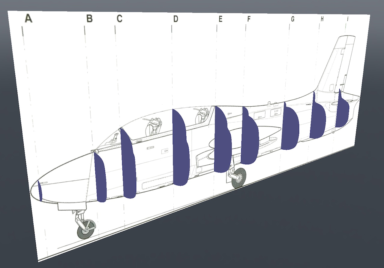
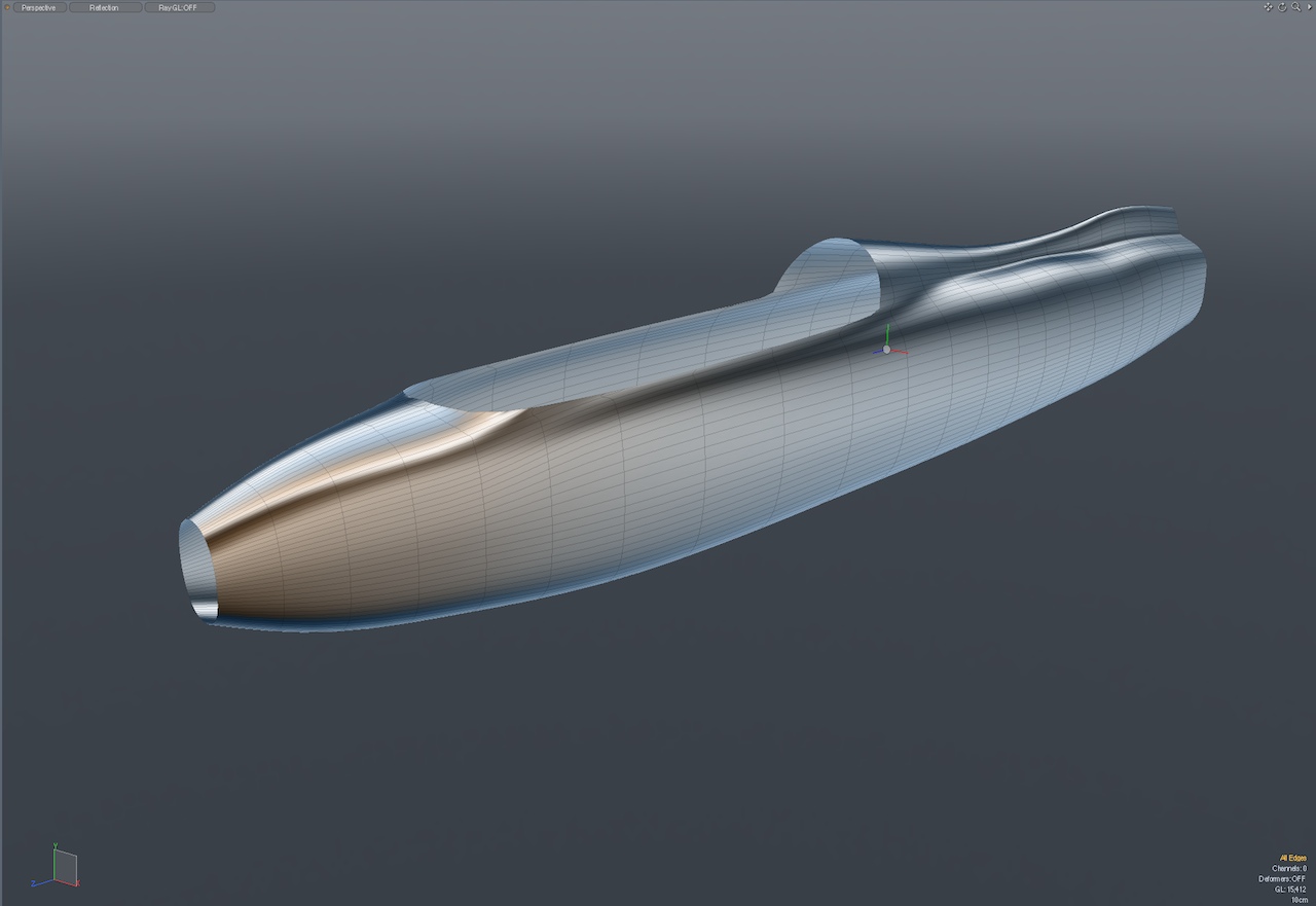
Fuselage:
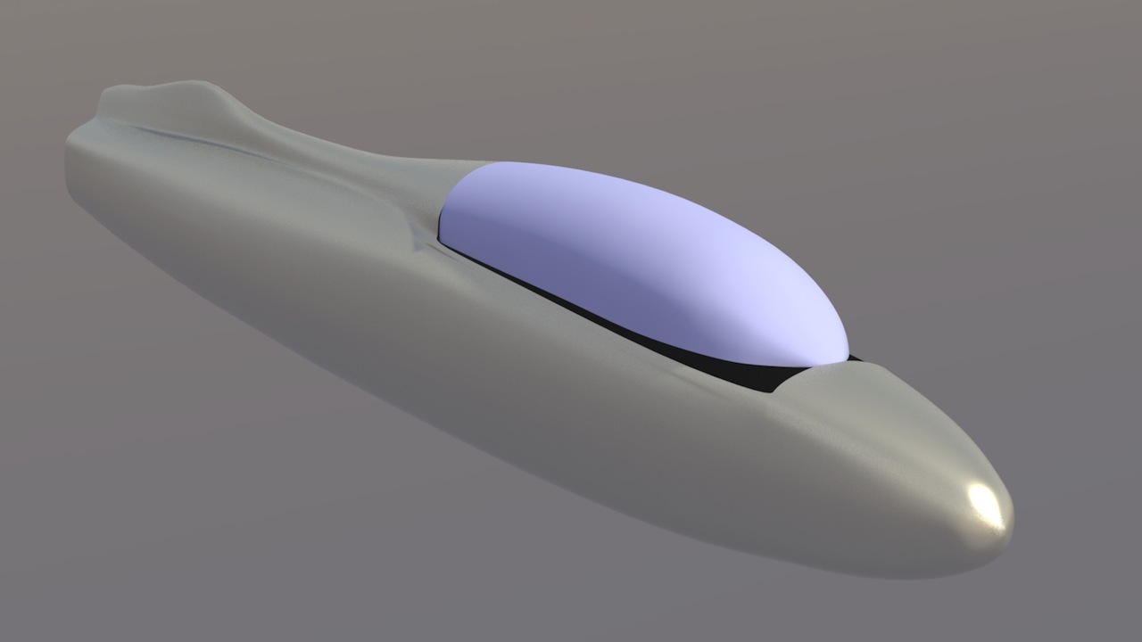
I used a 24-sided polygon for each of the fuselage cross sections, so that later, they can be bridged properly. (shown here in sub-d mode)
After bridging all the fuselage cross sections, I have this shape. It's close, but will need some adjusting.
I've done the same for the canopy, but in a separate mesh, for greater control. It's close, but not quite matching with the fuselage, due to the sub-d curves.
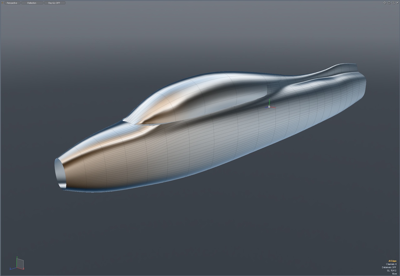
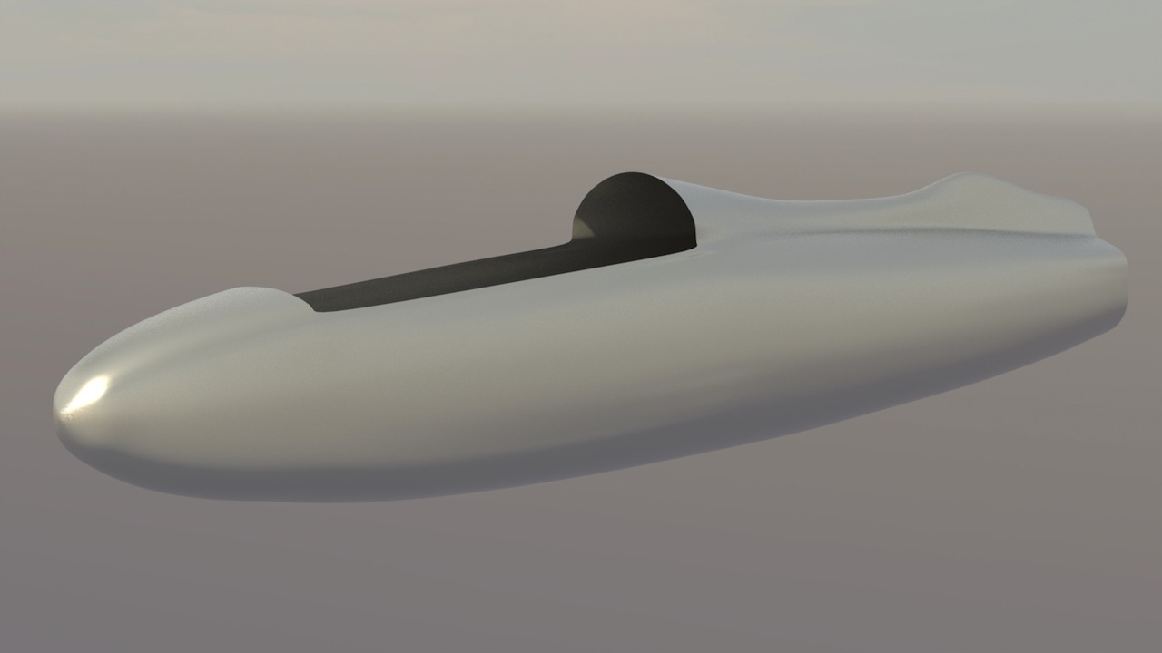
Updates on the fuselage and canopy meshes.
At this point, I'm not too concerned with the mating edges of the fuselage and canopy. The focus here is on getting each of those shapes as close to final as possible, before freezing them to hard polygons.
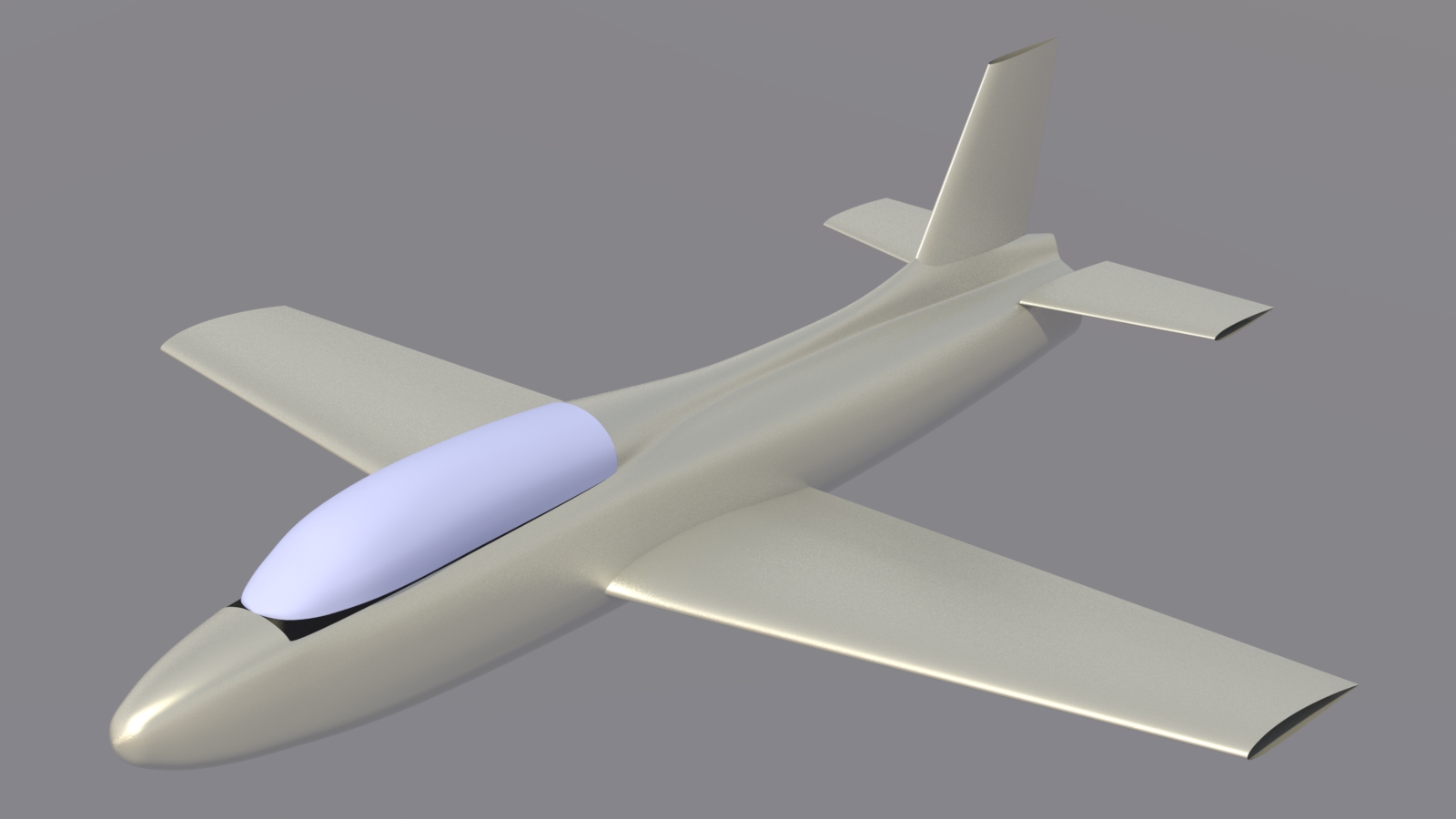
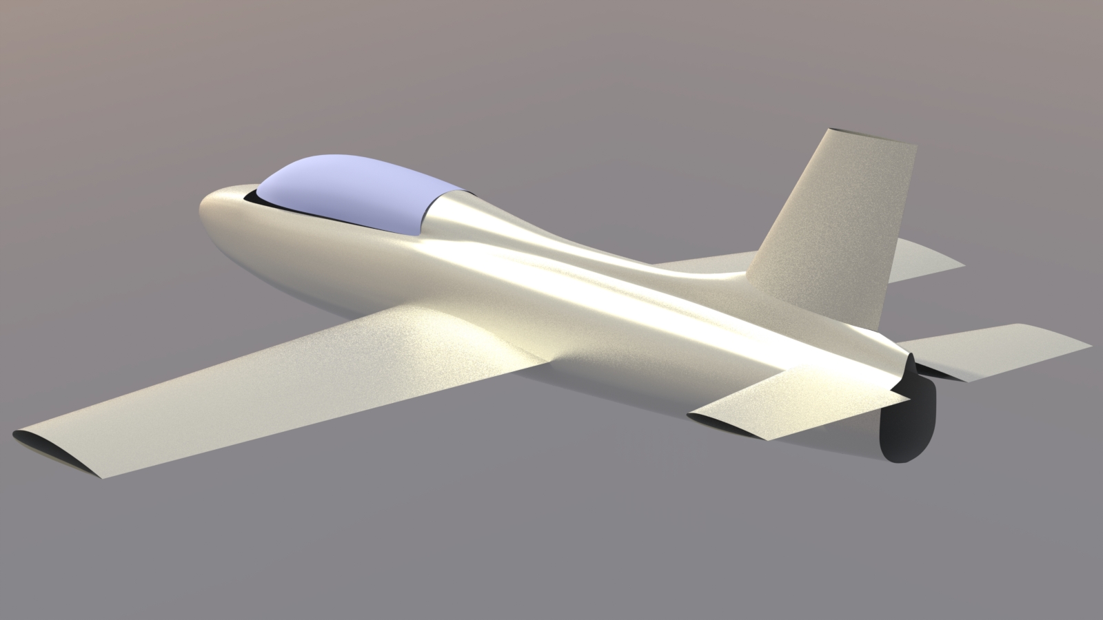
Flying surfaces
The flying surfaces have been created and placed in position. At this point, they're just primitives There are no tips on any of the flying surfaces, and the wings don't have any dihedral yet. They'll remain "flat" until the control surfaces are cut out.
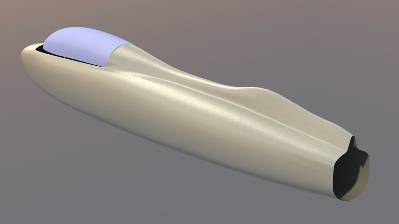
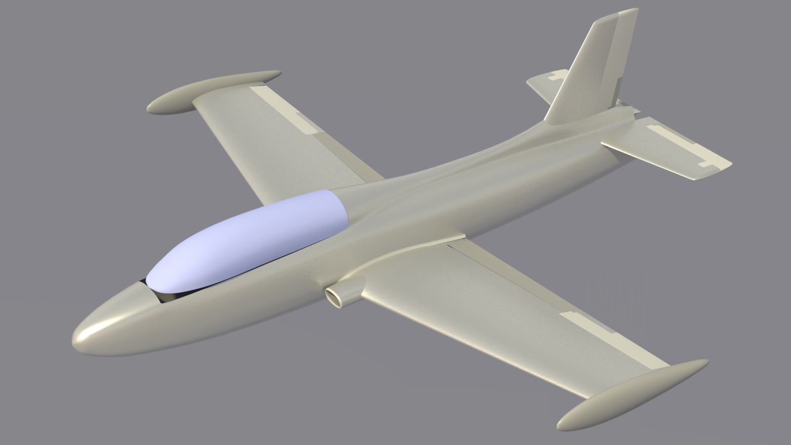
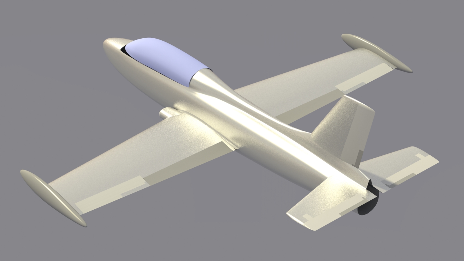
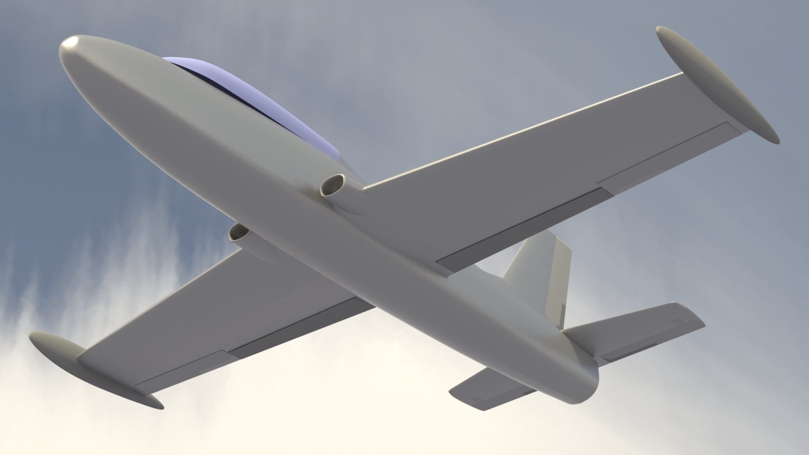
Details
All the control surfaces, including their trim tabs, have been cut out, and the wings have been rotated to their correct dihedral. I've also added the jet inlets, the wing/fuselage fairing, and have started on the wingtip tanks The color differences shown here, for the control surfaces are just for clarity, since their leading edges haven't been added yet. Next, I'll be working on final shaping of of the canopy mesh, and joining it to the fuselage.
Click the "Page 02" link below, to continue.