NOTE: I am not at liberty to redistribute the documentation used to build this model.
2015 F-22 "Raptor" High Resolution Project
The Plan:
The Plan:
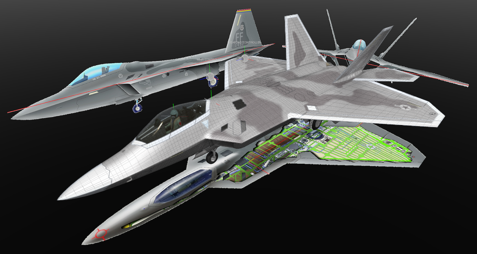
The F-22 is still a highly-classified aircraft, but it has been in the public view for a few years now, so there are more photos and other information available than when I built the previous models. On close examination of the manufacturing photos I have, it's clear that the fuselage is built in three main sections, as shown below. There are many reasons that they do it that way, and using some of those methods will benefit the 3D model as well.
For my main reference materials, I'll be using the same Lockheed Martin drawings I obtained years ago, because I believe they're as accurate as any available to the public. Those, combined with new photos, including those that I shot here in Anchorage of our F-22 squadron, will provide a lot of detail. Some of the new geometry will be re-topologized over existing parts from the 2013 model, using Psubs, and most of it will be rebuilt from scratch. (including the internal structures, which are minimal in the 2013 model. Below, a screenshot from MODO, showing where I'm starting, with the previous model in place, aligned to the reference drawings.
How Lockheed Martin and the Air Force cause me headaches...
I do each project differently, trying to emulate how the actual aircraft was built. For example, if it’s a fabric-covered vintage airplane, I’d generally build the framework first, then connect that framework with patches. If it’s an airliner or modern business jet, I’d generally start with cross sections, and connect them, to form the exterior first. I’ve also used spline cages and patches, but that wouldn’t be my choice for the F-22. With most aircraft, any of those methods is relatively straightforward, because the shapes tend to be smooth, and the panel seams that exist tend to be rectangular. My Piaggio P180 project, for example, wasn’t especially difficult to do in Psubs (although it took more time than hard polys) thanks to the smooth curves.
Any modern stealth aircraft poses a different problem. (F-22, F-35, various UCAV’s, etc.) That is, in a general way, they’re MUCH smoother than aircraft of the past. (for both drag reduction and stealth) But the problem of course, especially in Psubs, is that those smooth surfaces are composed of panels with very sharp, sawtoothed edges. I could simply remodel the exterior and emulate that with textures, but the issue there is that many of those are movable doors that I want to animate. So, actual geometry will be used.
With the exception of a few minor corrections I’ve learned about, I’m pretty happy with the exterior shape of my existing model. But, it’s not just a matter of “converting” it to Psubs, via some form of re-topology. I wouldn’t bother to redo this project unless I believed that the new one would be substantially better, and the particular thing that would make it better is the improvement of what some modelers would call the “texture”. That is something that will drive you batty on this airplane. Lockheed Martin and the Air Force both do everything they can to disguise the actual shape from onlookers, and you won’t find “factory cross sections” like you can for the F-15 or F-16. Unfortunately, those days are gone forever, especially for military projects, since stealth will always be part of the design. For example, there is dark-colored paint used to disguise the various convex “bumps” on the exterior to make them look less convex, and light-colored paint used on concave surfaces, to make them look less concave.The viewer’s glancing angle makes it even trickier. (Reflections disagree, in many cases, with what the paint tells your eyes.)
There’s a variety of materials used on the exterior, including steel, aluminum, titanium, and some very large composite pieces. (The entire exterior surfaces of the horizontal tail pieces are composite, for example.) As I mentioned before, it’s not these material’s individual (non-uniform) properties that give me a headache. It’s the more-uniform, but still “tricky” paint that goes over them.
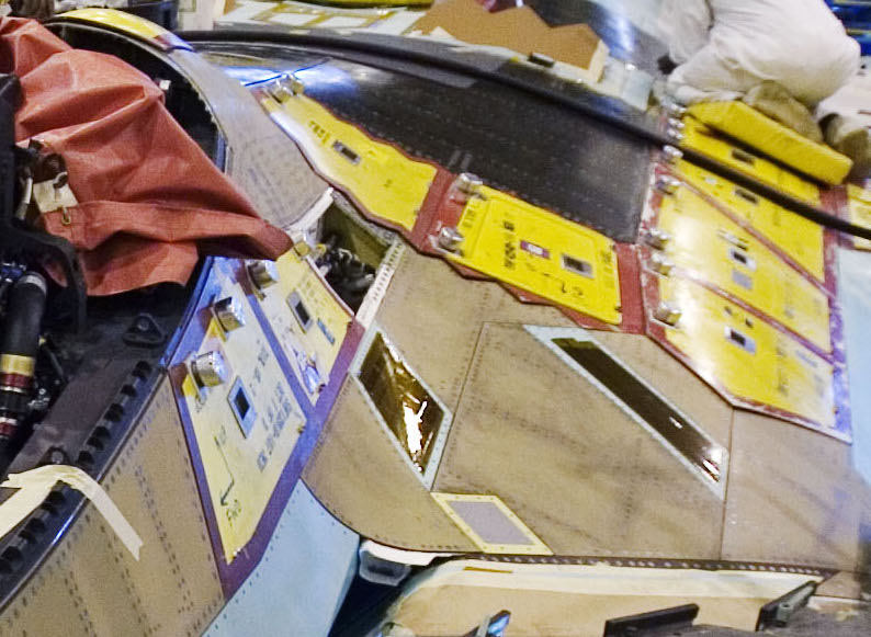
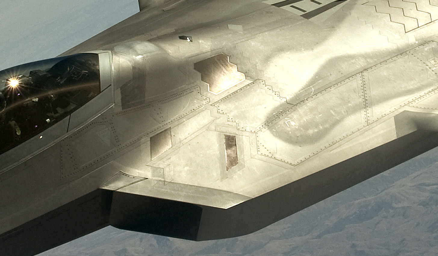
Have a look at this example, which focuses on an area beginning at the aft end of the canopy, and extends back to where the large (black) composite panels start.
In the first photo, taken during assembly, you can see some panels (yellow, with red outline) being held in place with what looks like knurled tensioning knobs. My first thought was that these were actual parts, waiting to be screwed down. But, "Baroba" on The Foundry forums thought they might be some kind of temporary covers, to protect the plane. I believe he's right, because I don't see any holes drilled around the perimeter for screws, and they also look "used", which makes sense if they're temporary covers.
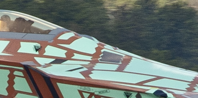
In the second photo, you can see what the aircraft looks like when it leaves the factory for test flights. At this stage, it looks like it’s made of only two materials, having been covered in some sort of “primer”, leaving those raised edges colored a reddish brown. It's then painted before delivery to the Air Force.
In the third photo, you can see how it looks in service. The paint now makes it look like it’s entirely made of metal, and you can still see a subtle hint of those raised border edges. Having seen some of these locally, (I live in Anchorage, Alaska, where we have a squadron of F-22s.) I know that the paint (or “coating”, as it’s often called) can sometimes be quite thick, and often varies quite a bit from one aircraft to another. The comment I've heard most often about this is that the aircraft can perform well in any of those states, but for missions where stealth is of higher performance, the coatings get updated just prior to the mission.
These challenges are specifically the ones I want to address with this model. If I can create all of those panels more accurately, then it will have been worth it. I’ll do the interior structures after that’s finalized.
There’s one more thing… Like any fighter, the F-22 is built in “blocks”, which include improvements over time. Some of these are really subtle, and so when I look at photos, I always have to keep the block number in mind. (and again, those involved don’t especially want us to know this at a glance)
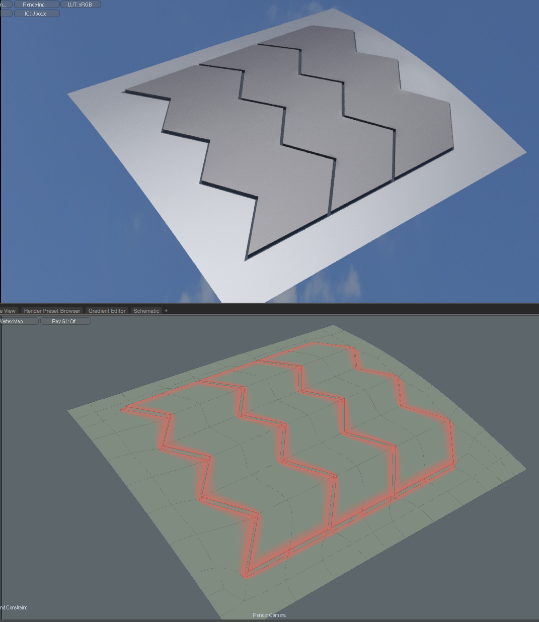
An example of how those panels can be created:
I copied a piece of the existing fuselage, just behind the canopy, and re-topologized it, to have more evenly-shaped (square) polygons, and then background-constrained the sawtoothed panel to it. Then I deleted the underlying polygons, and stitched this test panel into it. Once I applied some edge-weighting, (20%) it seems to work fine, even when I beveled it out a bit to see the effect. (This is in Psub mode.)
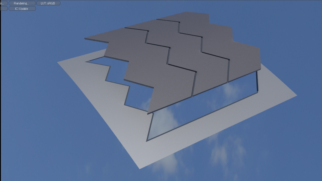
The tricky part is going to be planning the geometry that surrounds these panels. It won't be "easy", but I still believe it can be done.
Bonus... One of my favorite things about edge-weighting is that when you cut parts out at the weighted edges, it "sticks" to both parts. So, I can stitch the moveable panels in, cut and paste them, and animate them.
Primary Geometry First:
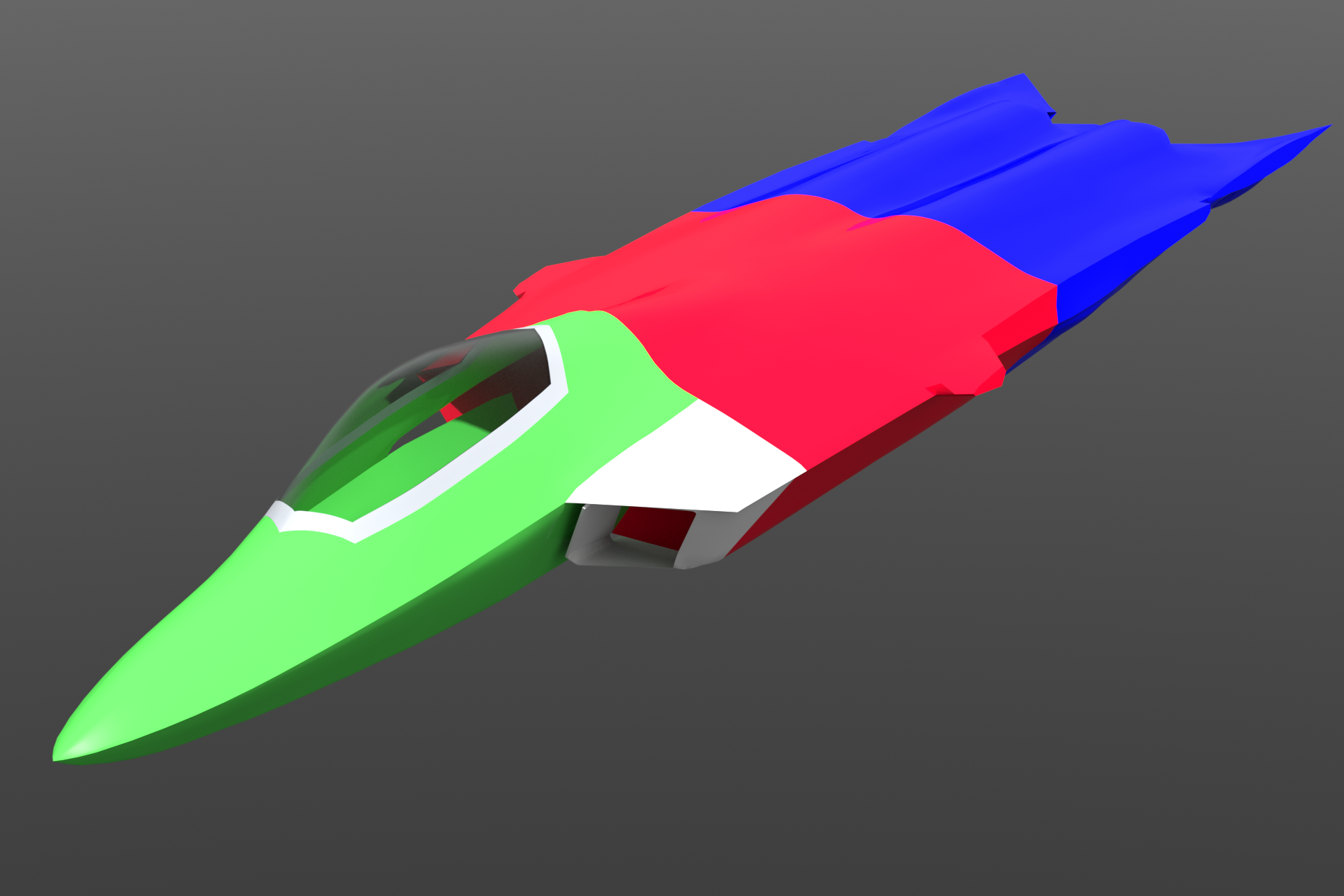
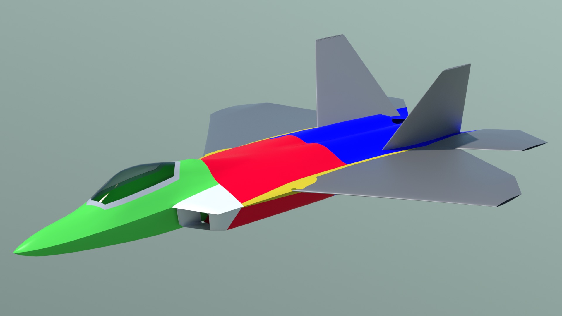
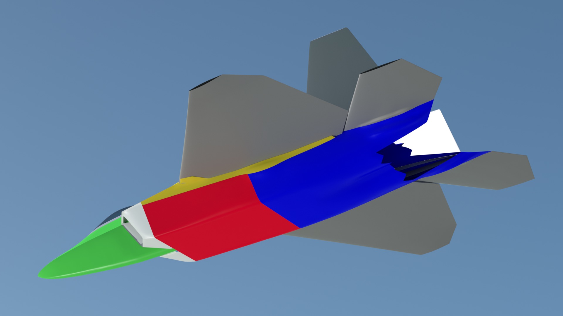
Since this is a rebuild, I'm most concerned with building all the external shapes in Psubs mode first, correcting small discrepancies as I go. As you can see from the color scheme, I've separated the major parts into the same primary sections that Lockheed Martin uses to build the aircraft. I've also replaced the wings and tail surfaces with new, uncut parts. They're already in Psubs mode, but the fuselage parts are hard polys, and I'll re-topologize over them. The engines and thrust-vectoring parts aren't needed at this point, so I've turned them off.
Once I have all these major fuselage pieces rebuilt in Psubs mode, I'll start adding the external panels. The plan is to add the panels one at a time, using "Background Constraint" to stick them to the fuselage. These will gradually replace the outer skin. The details on the wings and tail parts will be done the same way, later, and then the internal structures will be added, using the completed exterior as a reference.
Video update:
Thanks to MODO's background constraint, the rebuilding of the primary parts has gone faster than expected.
Click here to view a video showing the initial rebuild in 1080p, or Click here to view it in 720p.
Press the "Page 03" link below, to continue.