NOTE: I am not at liberty to redistribute the documentation used to build this model.
F-22 "Raptor" Project (2013)
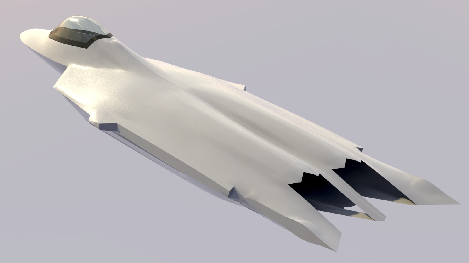
Perspective is everything...
Perspective is everything...
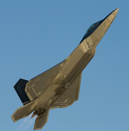 Making the decision to build a new F-22 model wasn't an easy one. This kind of modern stealthy aircraft has a huge amount of geometric detail that is different from practically all the other aircraft I've modeled. It's not obvious from a distant viewpoint, but when you start to discover what's going on, it's beautiful, from a design point of view, and a bit scary, from a modeling point of view. One of the most striking things to me is how quickly this aircraft appears to have been redesigned, following the YF-22 (prototype) program. (apparently, in only about one year) Paraphrasing one Air Force officer's statement, "As you walk around the aircraft, you begin to see that every aspect of the aircraft has been optimized for it's particular function."
Like any super-advanced project, the F-22 has had some problems... mostly related to software that controls virtually everything it can do. But, as a flying machine, it is one of the most well thought-out aircraft on the planet. I don't have any "insider" information, and couldn't share it here even if I did, but I'll point out some of those brilliant design aspects as we go through the rest of this article. If you love aircraft design, I'm sure you'll appreciate how many of these things have been done.
All-aspect stealth:
While some aircraft are optimized to be stealthy from certain angles, the F-22 apparently has "all-aspect" stealth. Modeling the aircraft reveals some of the things done to ensure that, and it's quite interesting. Anyone who has read a bit about stealth technology knows that there are several areas to consider, including:
- Acoustic (reducing sound the aircraft produces)
- Thermal (reducing heat signatures the aircraft produces)
- Radar (reducing the ability of an enemy to see the aircraft on radar)
- I'd add one more, relevant in the unusual close-in fight, which is "visual ambiguity".
Although radar detection is more complex than what I describe here, the most basic principal is easy to understand. If you've ever played billiards, for example, you understand how objects bounce around when they strike a surface. In it's simplest form, you can then visualize how radar waves might bounce off the angled surfaces of a stealthy aircraft.
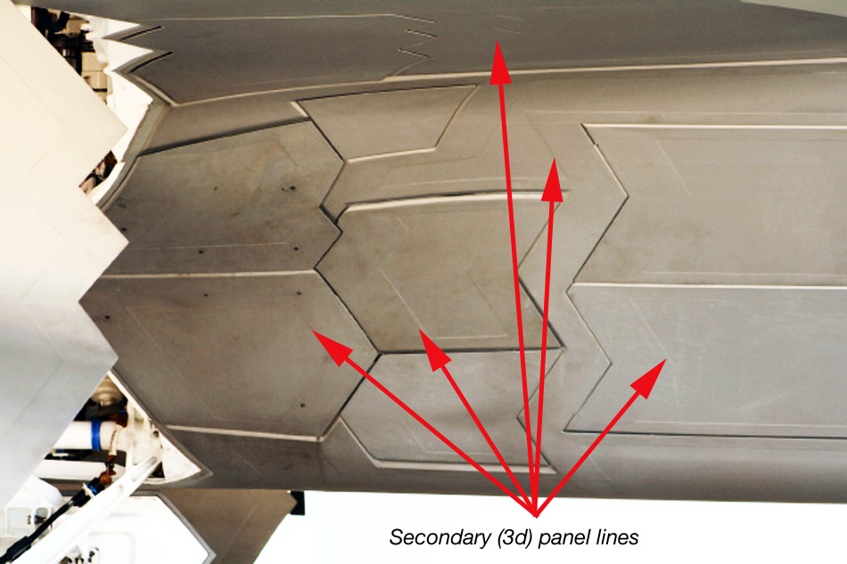
As you model an aircraft like this, you begin to see some the things that were done to aid in radar reflectivity, and there are MANY of them! The fit and finish of parts on this aircraft is nothing short of amazing. In fact, I think the coatings hide the manufacturing precision. Have a look at any panel on the F-22, and you may, depending on the state of it's coatings, see what we're used to describing as "panel lines". But, look closer, and you'll see that there are actually several panel lines (which are 3D shapes) around each of the more obvious "main" panels. I began to think of it as a "fractal" effect, as the project progressed.
The image below (with increased contrast, for clarity) is one of my favorite examples. The lines we traditionally refer to as "panel lines" are the actual seams. But first, notice that none of these are the traditional 90-degree (square-ish) lines that we see on other aircraft. Then, notice that both inside and outside these lines, there are other shapes, presumably designed to reflect radar waves away from those seams. Regardless of the actual purpose of these, they present quite a challenge to someone wanting to model them. First, you have to find them, which isn't easy, depending on the state of the coatings. More than just "lines", these are 3-dimensional, beveled shapes, and they occur at virtually every seam on the aircraft. So, the idea of modeling them all might not be practical. I've chosen to model what I think are the most prominent ones, and will periodically update the model, including others, as I discover them. It's my intention to do as much of that as possible using actual geometry, rather than texture maps. That way, when I find errors, I can correct them on a more permanent basis, rather than trying to re-paint a bump map.
There are many "ordinary" shapes on the aircraft that further disguise it's true shape. All of the tips on the wings and tail surfaces are beveled, for example, making all those surfaces appear thinner, at first glance, than they actually are. There are many shapes that appear as straight lines from some angles, and curves, from other angles. And then there are all the effects of the coatings, which I mentioned on the first page of this article. At every point, steps were taken to hide the true shapes, and it's quite effective. This even extends to the landing gear doors, and it's difficult to find photos with angles showing the interior of the gear bays. It's frustrating, as a 3D modeler, but it's beautiful, as a concept, and it obviously works very well for it's role.
Unbelievable Smoothness:
Have a look at the F-22 on a flight line, and it may not strike you at first, but it is extraordinarily smooth. Large parts of the structure are single, molded pieces of composite (carbon) and equally-amazing large single formed pieces of metal. That's why it's drag is so low. ALL previous U.S. fighters were built using structures that had a lot of small panels, attached with rivets and screws. If you don't follow aerodynamics, it might surprise you that the single step of eliminating most of those panels, screws and rivets can cut the drag in half. They're small, individually, but when you have many of them on the exterior of an aircraft, the effect is cumulative, and matters a LOT. Check out this YouTube video, "4195 - The Last Raptor", for some rarely-seen views of the aircraft, showing this smoothness.
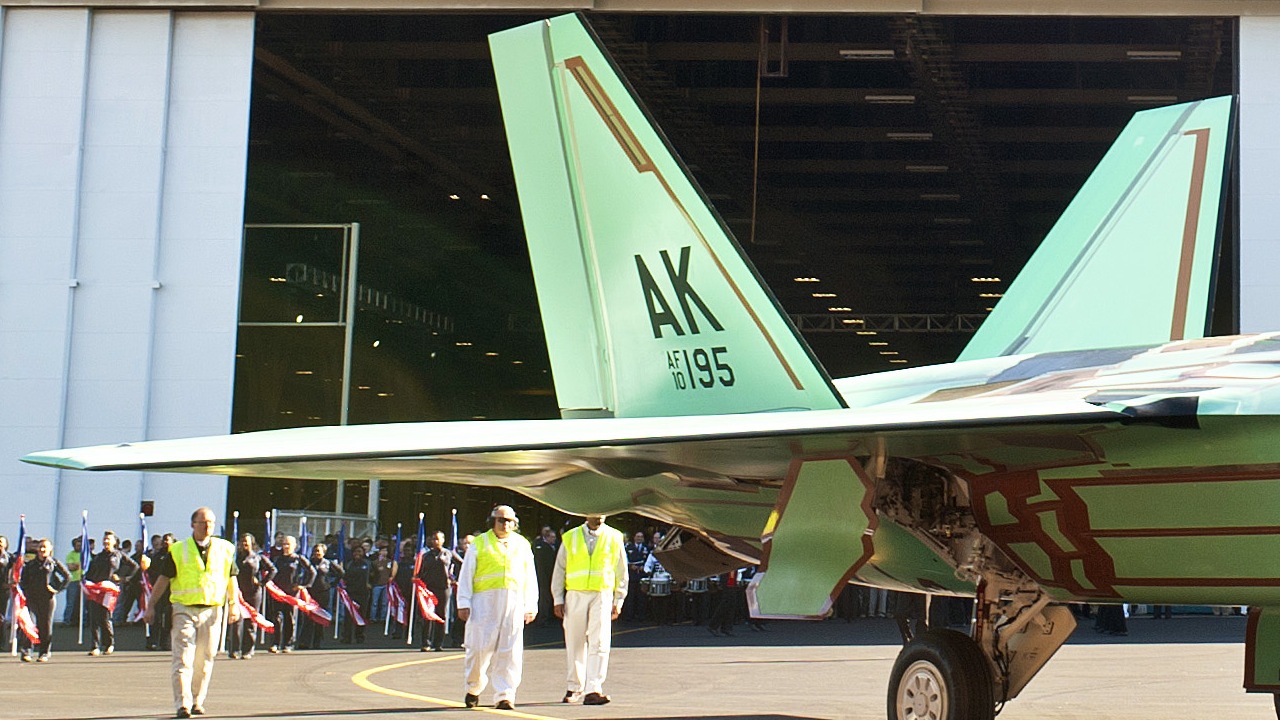
Lockheed Martin photo of the last F-22 produced
(Drag this image to your desktop to see the larger version, and check out how smooth this aircraft is.)
That means several things to a 3D modeler. First, the smoothness makes the specific shapes hard to identify visually, because you don't have the usual topographical panel and rivet lines to follow. (And, the markings and coatings intentionally disguise them further.) Notice how thin the tail surfaces look, for example, although they're "normal" thickness in real life. Fewer polygons (or texture maps) are required to simulate this kind of finish in 3D. In real life, it also means that the aircraft stays cleaner, because all those crevices that exist on other aircraft to gather dirt simply don't exist on the F-22. Even those parts that are assembled traditionally, using panels and rivets, are done to a much higher level of precision than most aircraft, resulting in very smooth seams and a great parts fit.
I can't help but appreciate something else, that has to do with the idea of using large composite panels. Think about how a typical metal airliner looks, on a hot day. On the ground, you'll see a lot of "rippled" reflections, due to those panels expanding in the heat. Notice when you look out the window at 30,000 feet, that all those metal panels have now shrunk, and the whole aircraft is "tightened up". Well... The F-22 is "tightened up" all the time, due to the use of composites and titanium. That helps with stealth, aerodynamics, and even maintenance. "Durability" over years, and in combat, has yet to be proven, but the test results look promising for that too.
How to begin?
 My approach with most subjects is to model the exterior shapes first, and to take the most time at that stage. By doing that, I'm left with a definite internal volume I trust, and everything else simply "must" fit. And... if it doesn't, it usually will point to an error in the exterior modeling that I will fix. (Always keep incremental backups!) I'll show some examples of this later.
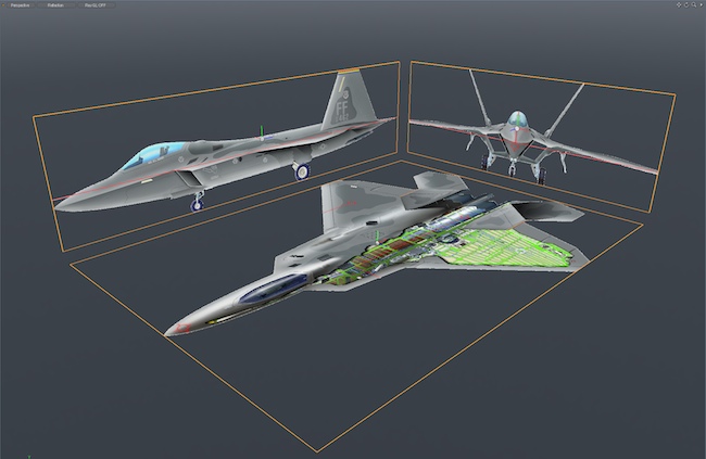
The first part I tackled was the fuselage, since everything else is connected to it. I used the published Lockheed Martin orthographic drawings shown here as a general reference. But, like most info on the F-22, these too are skewed, so every step in the modeling was double-checked against many photos.
As you can see, my previous model (below) gave me a reasonable start, and since the overall shape was right, I didn't rebuild the fuselage from scratch.
 Sparing you all the details, here are some of the things I did, to get it closer to what you'll see later:
- Deleted all previously-cut openings and panel lines, and re-bridged those areas, so I could reshape the fuselage freely
- Removed large sections from the center area of the fuselage, and re-bridged them, eliminating earlier errors ("lumps")
- Cut off the front intakes, and rebuilt them separately, before reattaching them
- Rebuilt the canopy area, correcting an earlier misunderstanding on it's overall shape
- Reshaped the lower aft end of the fuselage extensively, based on photos
- Spent endless hours, pushing edges and verts around, tweaking the shape while referring to photos - MODO's "reflection mode" was very helpful in spotting surface irregularities.
The F-22 fuselage is smoothly blended with the wings and horizontal tail surfaces. Rather than fake this, I went looking for information on the airfoils used on the actual aircraft. I found the following information in a couple of different places on the net, and it made a reasonable starting point: The root airfoil was listed as a NACA 64A?05.92, which is essentially a symmetrical airfoil, with several degrees of twist, from the root, (theoretically at the center of the fuselage) to the outboard tip. So, I bridged several plots of this airfoil through the fuselage, and blended the fuselage shape to accommodate that. Viewing as I mentioned above, it eventually looked right, and convinced me that the airfoil data was pretty close. Later, I would cut away the inboard (inside the fuselage) parts of the wing, using the fuselage itself as a boolean cutter.
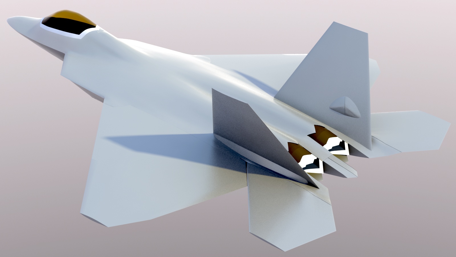
Once all those things were done, I had this shape, which was much closer to the actual aircraft. The need for further editing surfaced later, but at this stage, I could get a lot done with the other parts.
If you do a lot of manual editing on a high-res mesh, you will almost always end up with some "lumpiness", like the slight bumps you can see on the aft fuselage above, over the engine area. Later, when I show you the editing I did toward the end of the fuselage modeling, I'll also show you some tips to smooth these bumps. 3D modelers tend to like perfectly smooth surfaces, but in real life, even very smooth aircraft like the F-22 have a few of these lumps, caused by wear and tear, and by the extreme temperature changes that the aircraft go through on a constant basis. So, you might actually choose to leave some of these, as they will catch light in a way that's very similar to the actual aircraft. You decide. Of course, your materials and environment have a big affect on how all this looks, too.
It's also worth noting that the F-22 fuselage isn't bilaterally symmetrical. I mention this as an aspect of planning, when you model it in 3D. I chose to do nearly the whole fuselage with symmetry turned on, and only added the asymmetrical details (gun port, APU doors, etc.) at the end. If your 3D software allows modeling with symmetry, remember that once you start on those details, keep symmetry turned off!
Sit! Stay!
We all enjoy good training. So, it makes sense to train yourself, when you can. The example here is modeling the wings and tail surfaces for this aircraft, and I knew it would become tricky, for several reasons. I've designed and built actual RC aircraft and UAV's. so I always see these things as interesting, for their function, design, fabrication, practicality, durability, and quite honestly, how they look. In fact, I think that with a little knowledge, our brains become trained to instinctively "know" that something is right or wrong. To me, the F-22 looks very "right". An example we all go through is that over time, we become very familiar with our modeling subject. It doesn't take long to be able to recognize at a glance whether something's right or wrong. If you look at your 3D model, lit approximately like a reference photo, and the shadows and highlights don't match, it's not right. If they DO match, you're doing it right. If you notice these things, you'll model it more accurately, whether you have "data" or not. I think the ability to extrapolate, and to trust your results, is huge. It will become more true in the future, as data is more restricted, especially for military items.
We really are headed toward "stealthy robots against stealthy robots". The biggest people in aerospace have said that the F-22 and F-35 are probably the last manned fighters we'll see from the U.S.. As time goes on, this will become more true for land and sea vehicles too.
Solving a polygon flow problem...
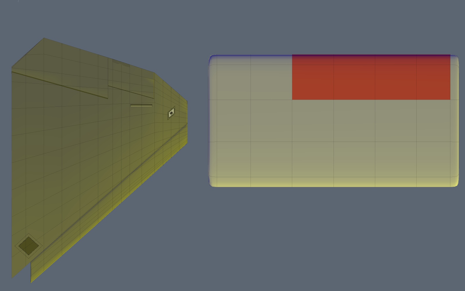
Take a look at the image below, showing the polygon flow on a traditional plank-type wing, compared to the F-22 wing. (I've colored some polygons on the traditional wing red, simulating where an aileron might go.) The F-22 wing's polygon arrangement is a result of bridging three different airfoil sections, each with the same number of edges. It achieves the shape we need, but presents a problem when it comes to cutting out and animating the control surfaces, because the polygons don't run along the hinge lines, as they do on the traditional wing. If you try to use typical tools here (like "edge extend", and scaling) to extend the leading edge of the flaps, for example, to create their leading edges, you'll create a mess of crossed edges, and they won't render smoothly. Or, you could try and build leading edges separately, then join them to the flaps. Again, this is problematic, because the existing leading edges of the control surfaces have an odd number of edges, thanks to the polygon flow and boolean cut. So, what do we do?
One answer to this problem is to use this wing as a background item, and using MODO's background constraint, rebuild it, creating a more suitable polygon flow. This works, but takes time you may not have. Luckily, MODO provides the tools you need to get around this problem quickly. Notice the dark-colored strip at the leading edge of the control surfaces? That's the place where I used MODO's "pen slice" tool to create a new edge that runs in the direction we need, parallel to the hinge line. From that edge forward, it's a simple matter to use "edge extend" as you would with the traditional wing, to extrude your leading edges, and it renders quite smoothly. Simple! (I'll show this process in a video later, as the article progresses.
"Simple" parts first:
I've built a LOT of aircraft in 3D, and none had the attributes of the F-22. These differences are the proof of it's advanced design. Many are "tricky" in 3D. The horizontal tail surfaces have an usual shape. The wing is a further example of the same problem, but with the added complication that it also has a built-in aerodynamic twist, along the X axis.
Complicating both parts is the addition of the "cats's eye" bulges that occur where there's an internal actuator. In engineering terms, "Short linkage distances are always better, more positive, and more powerful than long linkages." The result of that truism is that the horizontal surfaces ("tailerons", since they also move differentially) have their actuators right at the pivot point of the part they're controlling. And since those parts of the aircraft are relatively thin, a bulge in the surface is required. These bulges have to be efficient, stealthy, aerodynamic, and durable, on an aircraft that travels faster than the speed of sound, at something like 60,000 feet, and may be in combat under very serious engineering loads. Finally, the engines, the engine ducts, weapons, cockpit, and landing gear have to fit inside this structure, and externally, the shape has to remain both stealthy and aerodynamic. There are similar bulges at the main gear door locations.
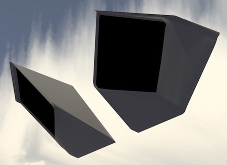
One of many interesting details... Notice in the photo below, how the bottom of the aircraft blends from a sharply angled shape at the front, to a smooth, curved shape toward the tail.
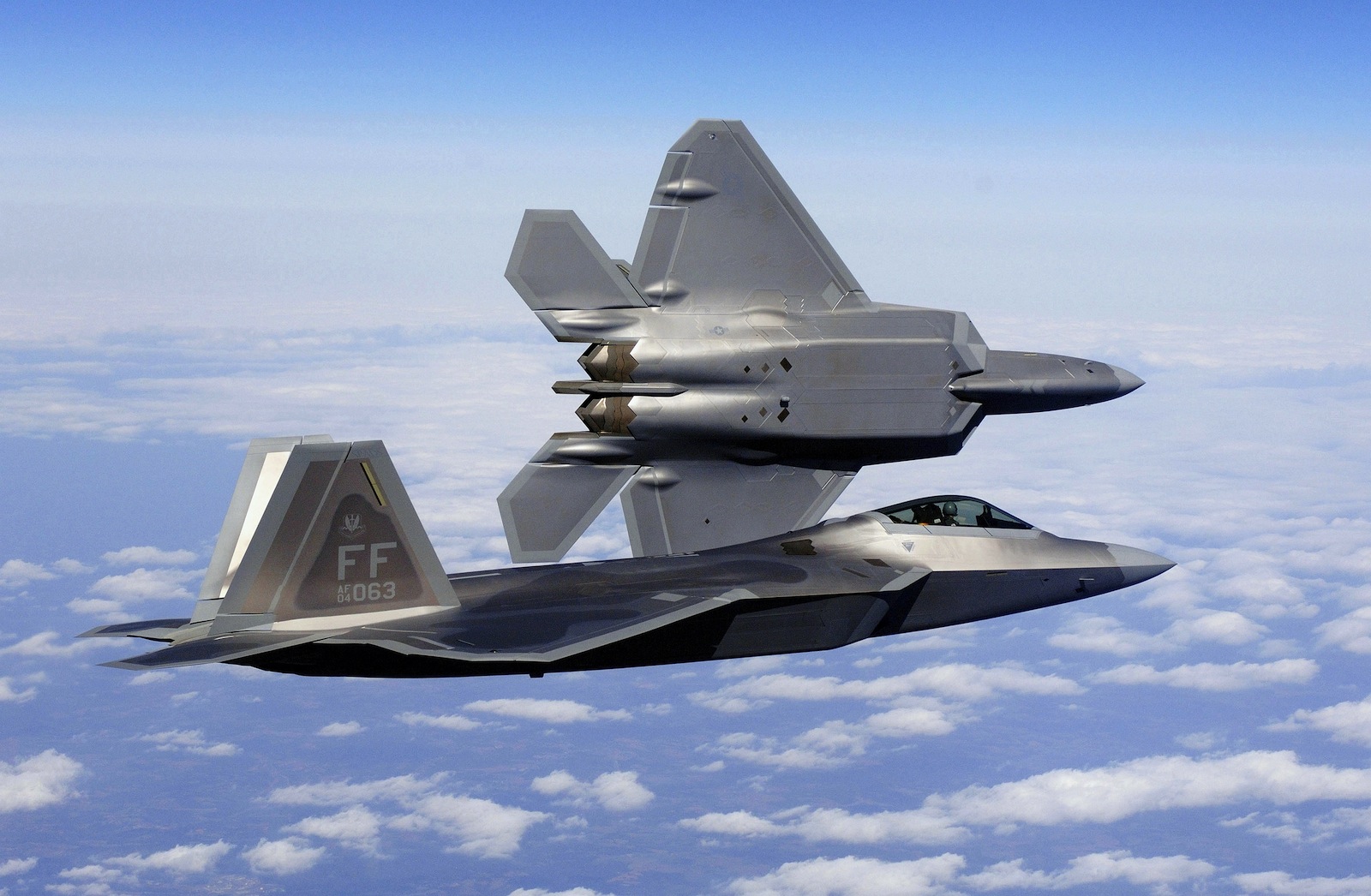
USAF photo
The tail surfaces were modeled next, by extruding plots of symmetrical airfoils. The vertical tail surfaces were the simplest, since they're composed of just a root and tip airfoil, bridged together. The horizontal tail surfaces were a bit more challenging, because their shape required three airfoil sections, rather than two. Here's where I first realized that the wings would be "tricky", because the wing also contains three primary sections, but in addition, includes several degrees of aerodynamic twist, around the X axis. The wing also the actuator bulges mentioned above, and adds flaps, ailerons, leading edge flaps, ("lefs") and doors for the landing gear. So, doing these things in order also provides some "training", as we go, prepares you for the next steps.
Often, the order you do things in is just as important as the modeling task itself. Here's the process I use often for wings.
- Build the airfoil-shaped exterior, by bridging airfoil plots (each with the same number of edges)
- Add the geometry for the actuator fairings/bulges (Here's where I used some unusual methods.)
- Cut the control surfaces into the wings, which will now include the actuator bulge halves. (leaving them in place)
- Move the control surfaces to their own mesh, before the next step.
- Check for any cleanup required, as a result of the boolean cuts. (Merge verts, etc.)
- Add any other geometry into the skin, such as lighting fixtures.
- Add beveled leading edges to the control surfaces., allowing them to rotate without overlapping (pre-rigging)
- Add recessed trailing edges to the wing surfaces, for the control surfaces to fit into. Interesting note here... On an aircraft where there are Fowler-type flaps, it's important to add these internal edges to the wings, because they'll show when the flaps are extended. On the F-22, this proved unnecessary, because the flaps simply rotate, and those internal edges would never be visible. (Ancient 3D axiom - "Don't model things that will never be seen. You're just wasting polygons.")
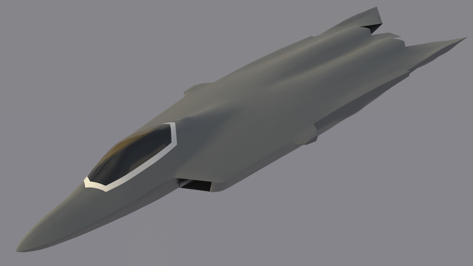
In the image below, the bulges mentioned above are still separate models, in the case of the vertical stabilizers, and are embedded primitives for the others. At this point, I realized I how could model them directly into the flying parts, (mentioned above) so that was next.
Making the "cat's eye" bulges
I tried several methods for creating these. Sculpting tools worked, but didn't give the precise shape and control of the polygons I wanted. I also tried various cylindrical and radial falloffs, which worked, but eventually chose to use proxy objects and a background constraint.
Proxy bulges were made for all the actuator fairings by "squishing" (scaling) sub-d spheres into appropriate shapes, and rotating and embedding them. They cross through the fuselage, (landing gear bulge, and taileron bulge) wings, (landing gear door bulges and actuator bulges for flaps and ailerons) and the vertical fins. (rudder actuator fairings)
These bulges, which blend with each other smoothly, and "telescope", in the case of the control surfaces, as hinge fairings) needed to be attached to their respective parts, just as they are on the actual aircraft. Otherwise, they couldn't be animated. I could attempt to model them separately, and parent them to the parts, but these bulges are smooth on the actual aircraft (molded carbon fiber) and separate geometry never looked right. It occurred to me that I could use MODO's "background constraint to help. Here's what I did.
In the video below, there are two examples of the method used. In both cases, I'm beginning with a frozen (hard-poly) wing, and two bulges, also frozen, which I've cut to fit, using the wing itself as a boolean cutter. That gave me the option of using those arts as separate, attached bulges, if needed.
I selected all the polygons around the bulge area, and using the "selection" action center, moved those polygons until they went past the bulge. Then, leaving them selected, I activated MODO's background constraint, (in "Vector" mode) and pushed the polygons back into place. The background constraint was then turned off, and the proxy bulge part was turned off, so any small adjustments could be made to the wing piece. With careful use of the background constraint, you might not have any adjustments to make. Notice I move the polygons more slowly with the second, higher-res version, to avoid smoothing errors.
I thought the low-res test was too rough, so In the second example, I simply did a "faceted subdivide" on the same polygons, and did the operation again. Once completed, the fairings are obviously much smoother, and by viewing the results with highly reflective materials, and/or extreme viewing angles, you can decide whether the mesh needs further adjustments. Toggling the wireframe off will often reveal bumps you can't see otherwise. Both examples here are using MODO's default smoothing angle of 40 degrees. You could increase the smoothing angle, or you could manually adjust the mesh. I prefer the manual method, so it will transfer to other software with no potential issues.
There's one other step I eventually took, not shown in the video. That is, I beveled this entire patch of denser polygons inward slightly, to do two things. First, it properly isolates those dense polygons from the surrounding wing, in case I chose to put the wing back in sub-d. (which I didn't) More importantly, it provides a thin strip of polygons around the area, so that when I adjust the bulges, those edges aren't selected, and therefore, there's no risk of screwing up the surrounding wing geometry, by moving the larger polygons.
The real beauty if this method is that at this stage, you don't even need a backup of the part. if you don't like the results, you can simply delete the edges, and your wing (or whatever part you're working on will revert to it's original shape. Now, when you make the boolean cuts to create the control surfaces, you'll have those bulges built in to each part, and they'll fit perfectly. By slightly scaling the aft one (the bulge on the control surface) you can create the slip-fit that exists on the actual aircraft, and it will look right when animated.
Click here for a brief movie showing the process. (Movie opens in a separate tab.)The Rig:
I've been rigging parts as I finish building them, so that it wouldn't all have to be done at once. So far, the rig includes:
- Wing trailing edge flaps
- Wing leading edge flaps
- Wing ailerons, which operate differentially or in unison
- Tailerons, which operate differentially or in unison
- Rudders, which operate differentially or in unison
- Engine thrust-vectoring paddles (operate in unison up or down, or differentially, for "parked" position
- Jet exhaust volume item (smoke) which can be turned off and on, and moves with thrust vectoring
- Afterburner function, using smaller internal volume with point lights
- Position lights on the wings
- Cockpit lighting, with brightness controls for the MFD's and HUD
- Taxi and landing lights, controllable independently
- Electroluminescent strips on fuselage, wings, and tail surfaces, for night operations
- Opening APU intake and APU exhaust doors
- Opening air refueling doors
- Opening and closing canopy, including a mechanism with a rotating jackscrew
- Retractable landing gear with sequencing doors (Wheels use revolve modifier for ground operations.)
- Nose wheel steering, for ground animation
- Opening and closing weapons bay doors. (I'll add internal details later.)
Here's a brief movie, showing the features of the model as of today.
Click the "Page 04" link below, to continue.