Northrop T-38 "Talon"
Rigging...
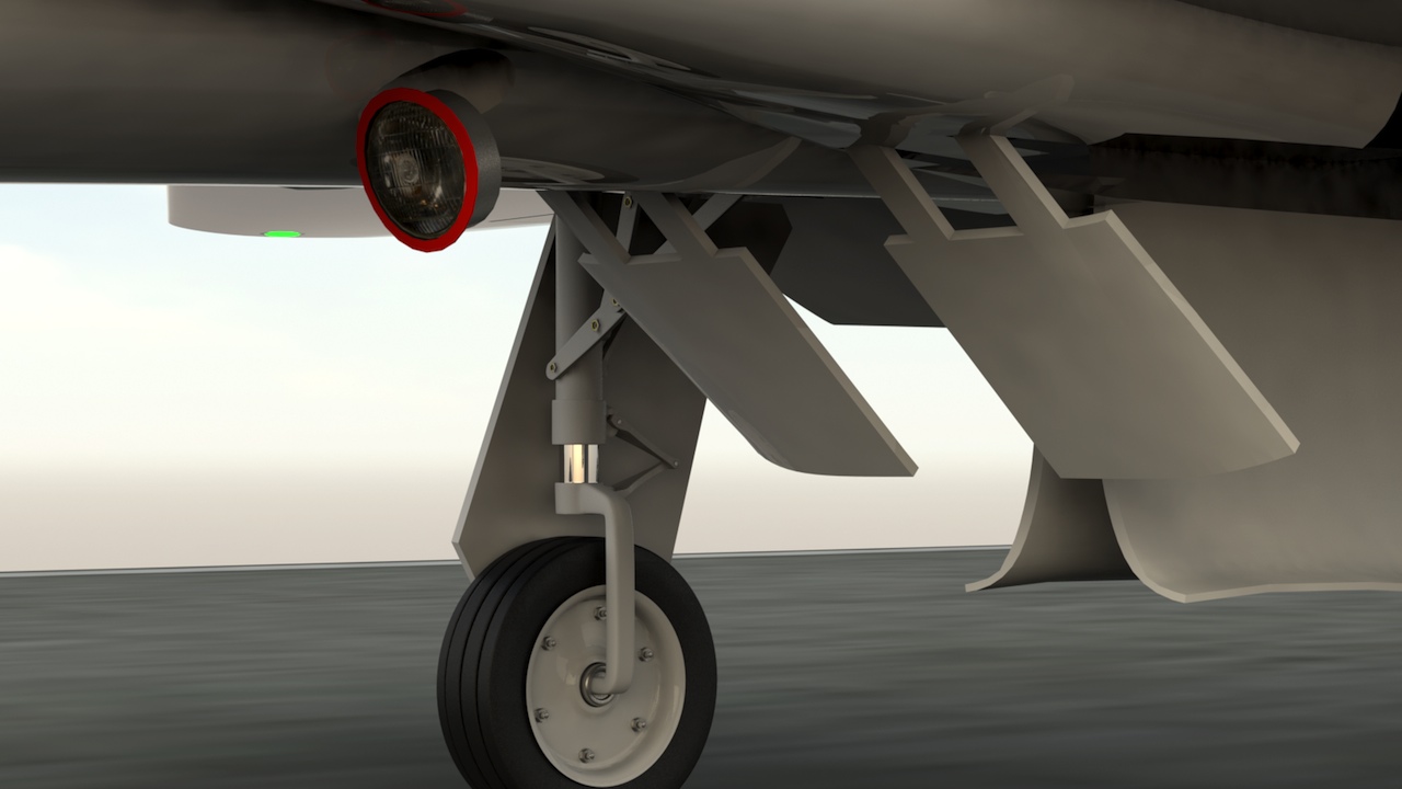
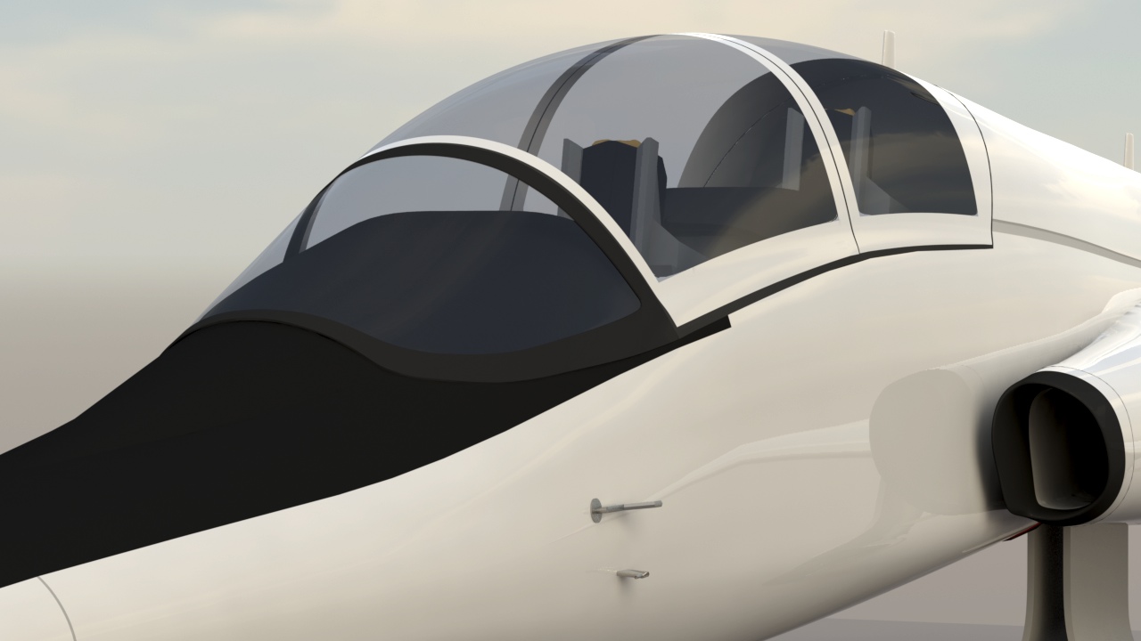
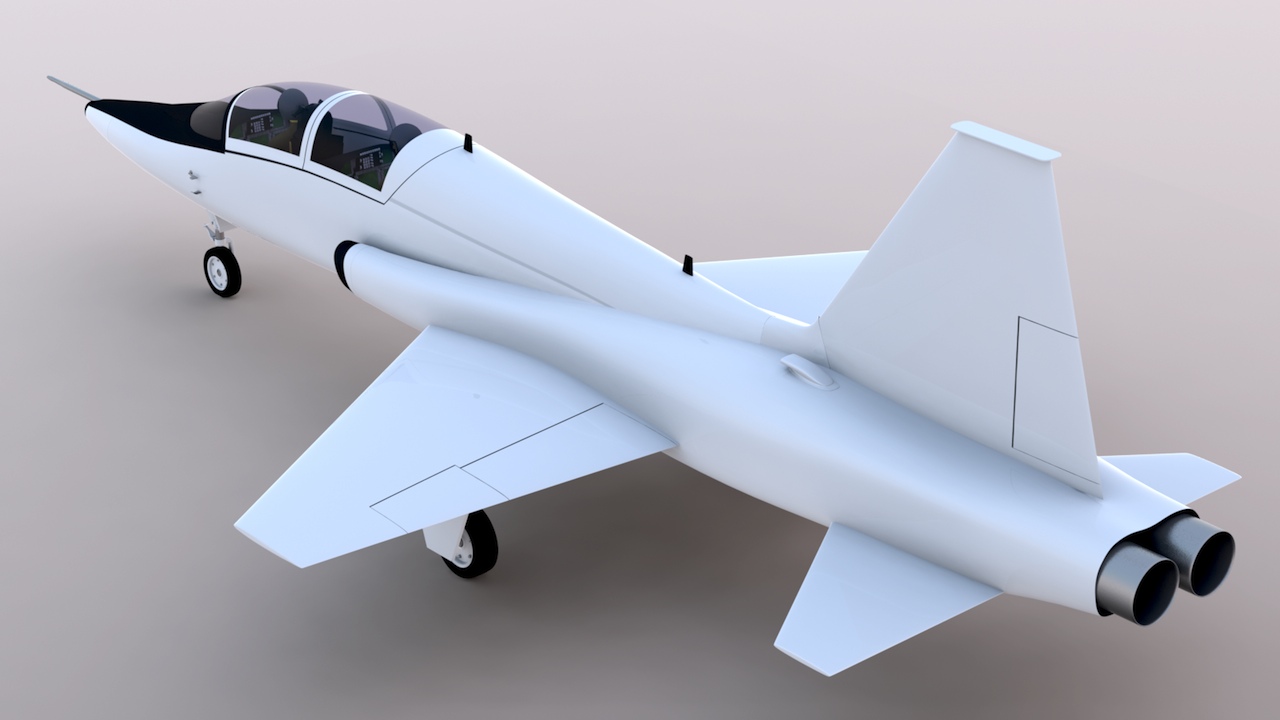
I've cut out and rigged all the control surfaces, the speed brakes, and even opening canopies. The landing gear doors are cut out, but this rigging will take some time, because there's a lot of linkage to hook up, and the main gear oleos have to be extended for the main wheels to reach the landing gear bays. (They're shown compressed in these renders, which is normal for being on the ground.) That's why the main gear doors aren't visible in the movie here. Click here for a movie showing the rigging I've done so far.
Here's a brief, high-speed flyby.
Documentation problems we all face:
When I model a real-world subject, I like to get great documentation, which gives a sense of gratification, knowing that the 3D model is accurate. But this simply isn't always possible. I find these issues on virtually every project I do.
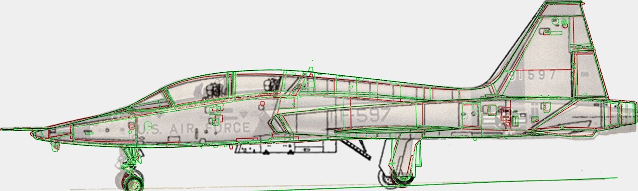
Have a look at the image below. It's a composite of four different side views, which all claim to be "scale drawings". (If you drag this onto your desktop, you can view the larger version, which is 1280 pixels wide.) One is outlined in black, one in red, one in green, and the fourth one is the light brownish-colored image. I've scaled them to the same overall length and height, and rotated them as needed, to try and get them to match. This isn't just about "details". The difference in the main landing gear location is critical, for example, because if it's wrong, then the gear won't fit into the wings and fuselage properly.
Although most of them seem to agree on the basic curves at the nose and tail, you can see that the biggest discrepancies are in the middle of the aircraft. This is a hint, as to how these were created. Chances are high that at least a couple of these were copied from paper, and/or projected from a transparency. Paper, of course, physically distorts. And having done it myself, I know that with optical projections, you get divergence of exactly this type, where the aircraft looks more (or less) "bent" along it's length.
In this example, I just lined up the fuselage parts, but these drawings (at the landing gear locations) also show a huge difference in the aircraft's "squat angle". (how it sits when on the ground) Most tricycle landing gear aircraft sit on the ground at a slightly nose-down angle, so that, on landing, they "stick" to the ground better, and on takeoff, they're not prone to rotating prematurely. Some of the drawings here show the aircraft sitting too nose-high. In the case of those drawings which were created from measuring the actual aircraft, it indicates that they most likely measured one that was completely empty of both fuel and crew. Measuring one in a static display, or in a museum, you must realize that it's probably missing other equipment too, which affects that.
But… These are all guesses. What we have to do as scale modelers is get the best documentation available, combined with as many photos and articles as we can find, and create our version of what we believe is accurate. Your brain, connected to your eyes, is far more accurate than you might imagine. Trust your judgement that when it looks right, it probably is. Use shadows, reflections, and other cues to help with the details. In my opinion, it's not worth it to continue trying to verify every single measurement, and in many cases, it simply isn't possible. My preference is to do the best I can, and then move on to the next project, rather than getting too bogged down with impossible problems.
A little lighting…
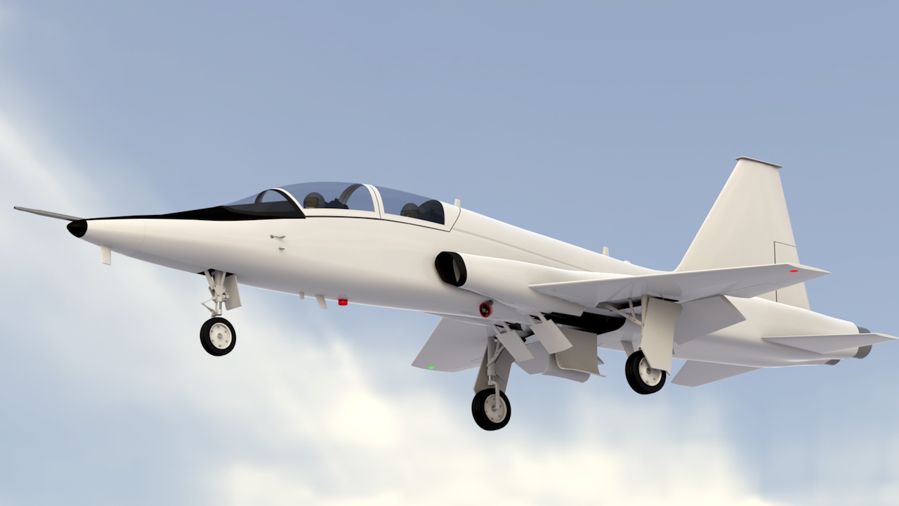
I've added some cockpit lighting, wing tip navigation lights, (red and green), a retractable landing light, and a rotating beacon. Here's a test animation.
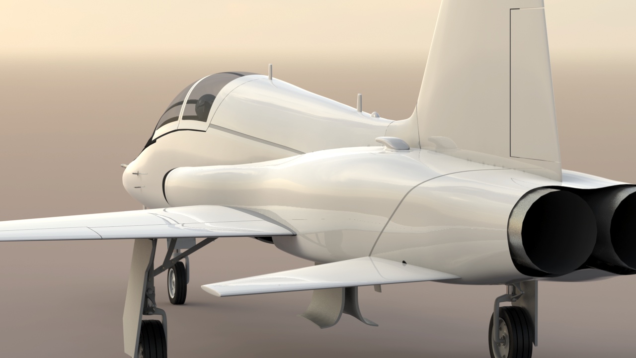
Details are coming along…