NOTE: I am not at liberty to redistribute the documentation used to build this model.
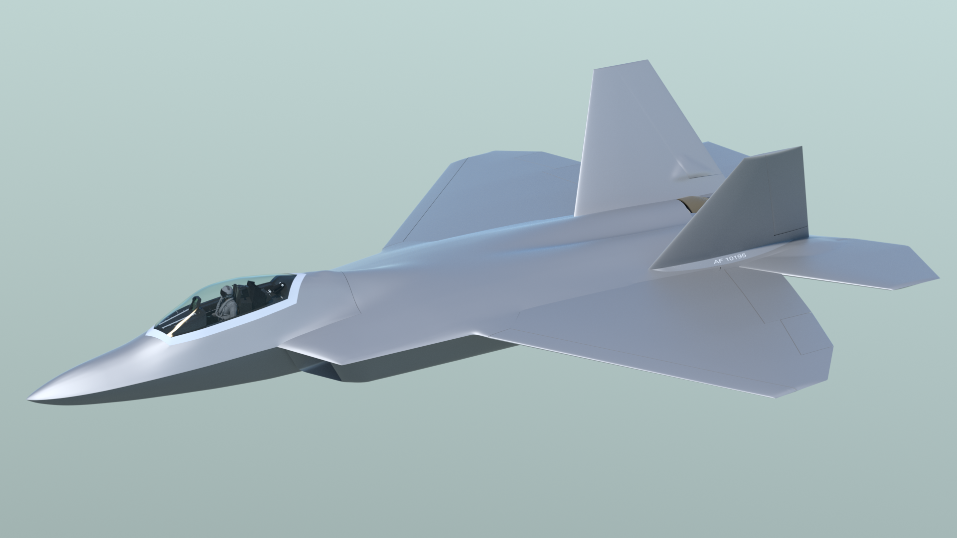
2015 F-22 "Raptor" High Resolution Project
The first major cutouts and panel tests:
As usual, these images are larger than what is displayed in your browser. To see more detail, drag them to your desktop.
The first major cutouts and panel tests:
As usual, these images are larger than what is displayed in your browser. To see more detail, drag them to your desktop.
Convinced that the fuselage and wings are smooth enough to proceed, I decided to cut out the main gear doors and nose gear doors first, because their shape (especially the main gear doors) is one of the trickier ones, and also sticking the panel outlines to them involves some odd angles. I first used boolean cutters to separate the landing gear doors, and then applied the perimeter panel polygons to the doors. Then, I slightly beveled the panels, to give them their 3D look. No surprises here, as this is a similar workflow to working with hard polygons and booleans, which I've done many times in the past.
The difference with my method this time is that I'm taking the time to repair the polygons around the boolean cuts, and then applying edge-weighting to them, (and the doors) to preserve their shape. The results with Psubs are quite encouraging, and I'm convinced that this method will work well for the rest of the model.
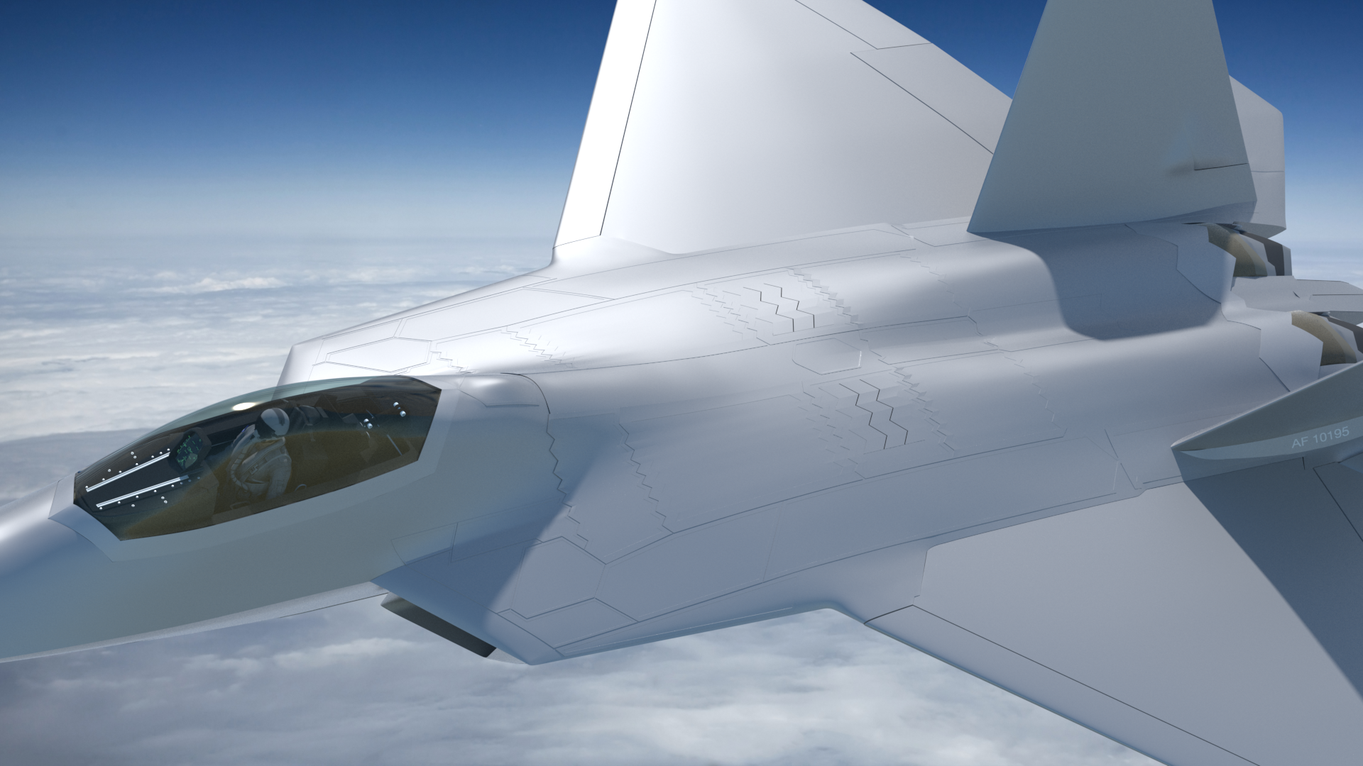
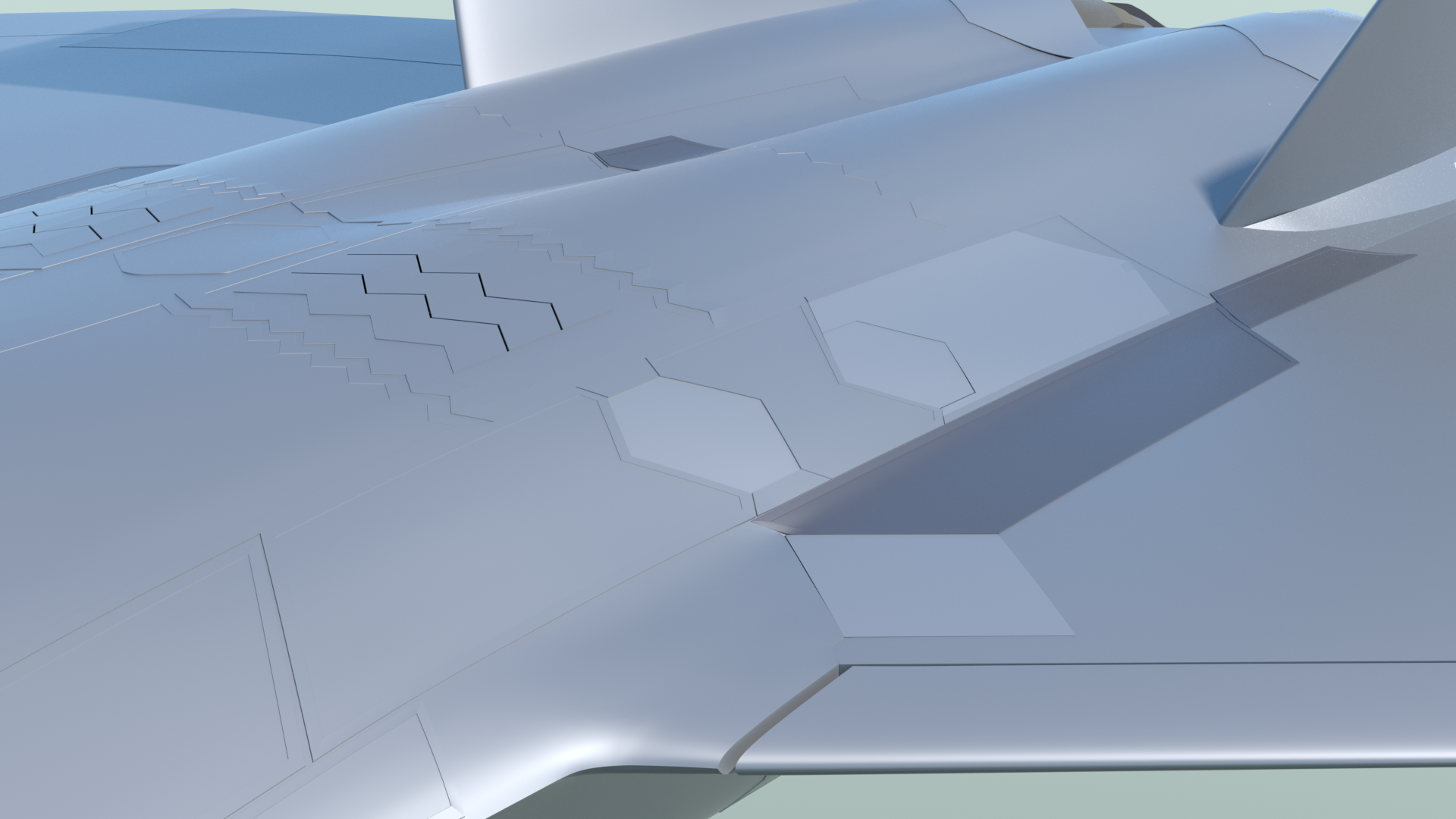
Really nice results... Smooth surfaces, but with the contrast of the sawtooth-edge panels.
More tests, which I'm pretty happy with, on the bottom fuselage panels. I'm starting to come up with some numbers to use, in regard to thickening and bevel amounts, so I can keep these consistent, around the aircraft.
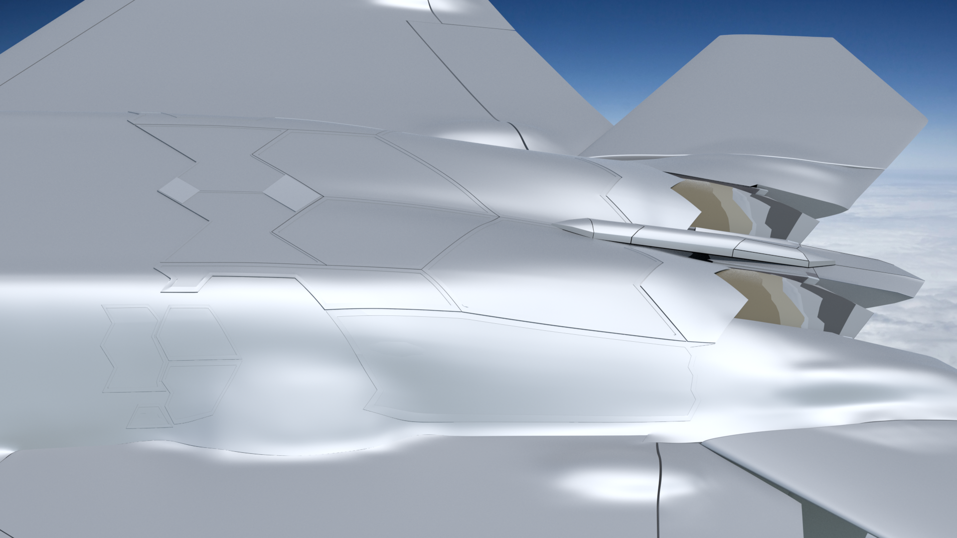
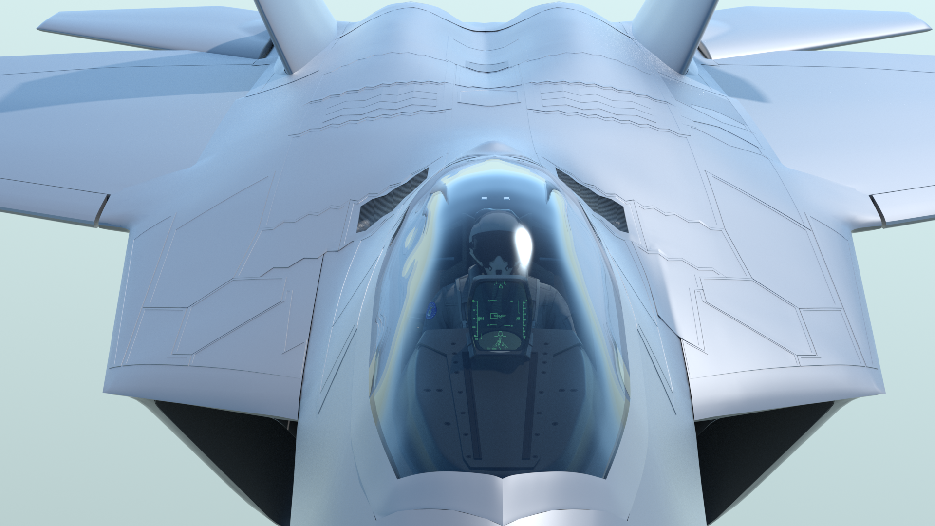
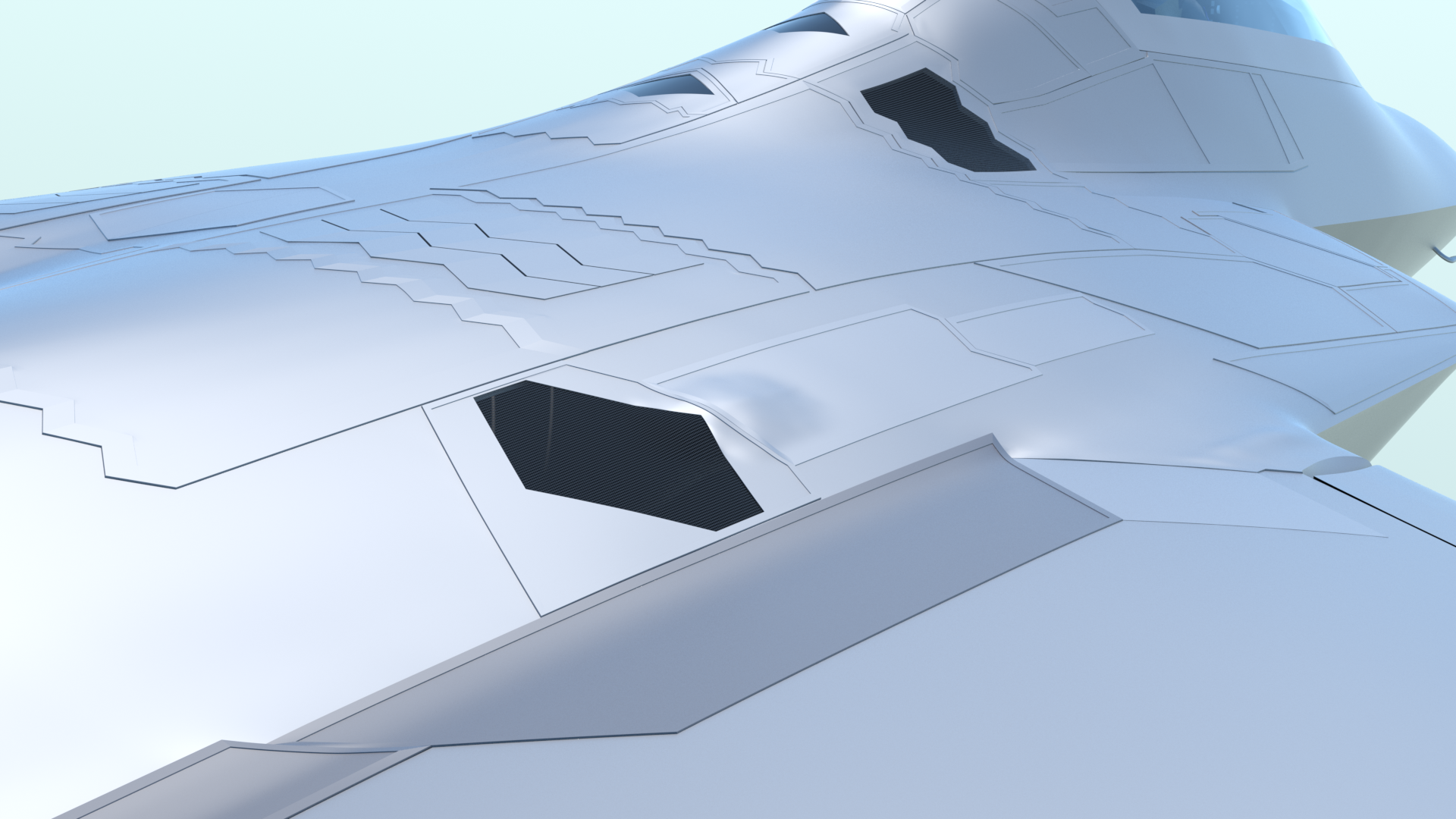
More work on the upper fuselage panels
This is challenging for sure, since some of the work has to be done by experimenting, based on reference photos. But, it's definitely achieving the look of the F-22, and I'm still quite pleased with the results in general.
Refining the panel method:
This is coming along nicely.
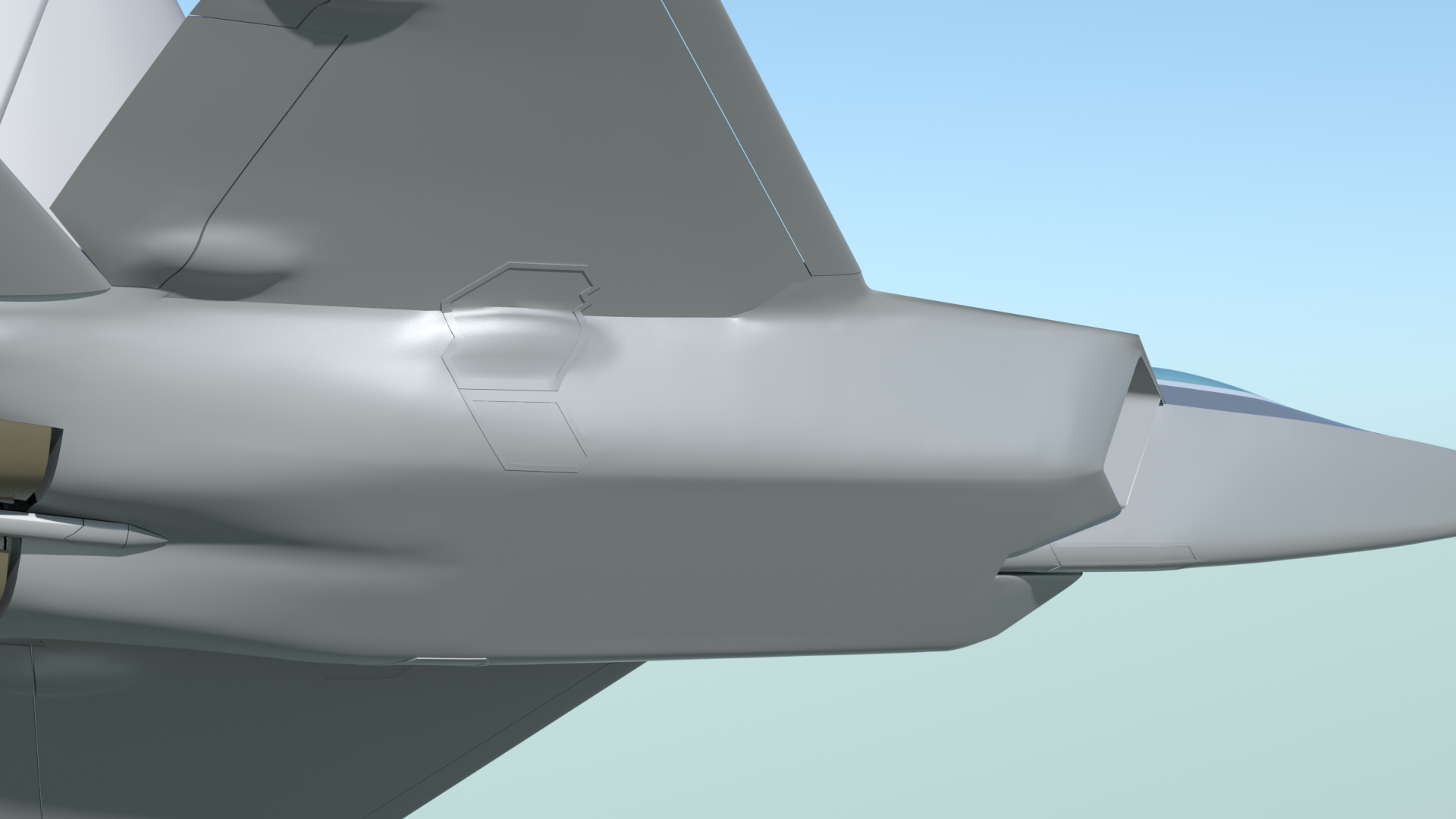
Occasionally, I’ll encounter a minor issue with some of these, due to a slight distortion from applying the base panel geometry with background constraint. But, these are easy to fix, (It only takes about 10 minutes per panel to redo them.) so the surface it getting better all the time. Ideally, these should all sit as close to each other as possible without overlapping, to simulate real-world screw-on panels.
I’m basically working my way forward toward the nose, which is why there aren’t panels directly under the cockpit at this time.
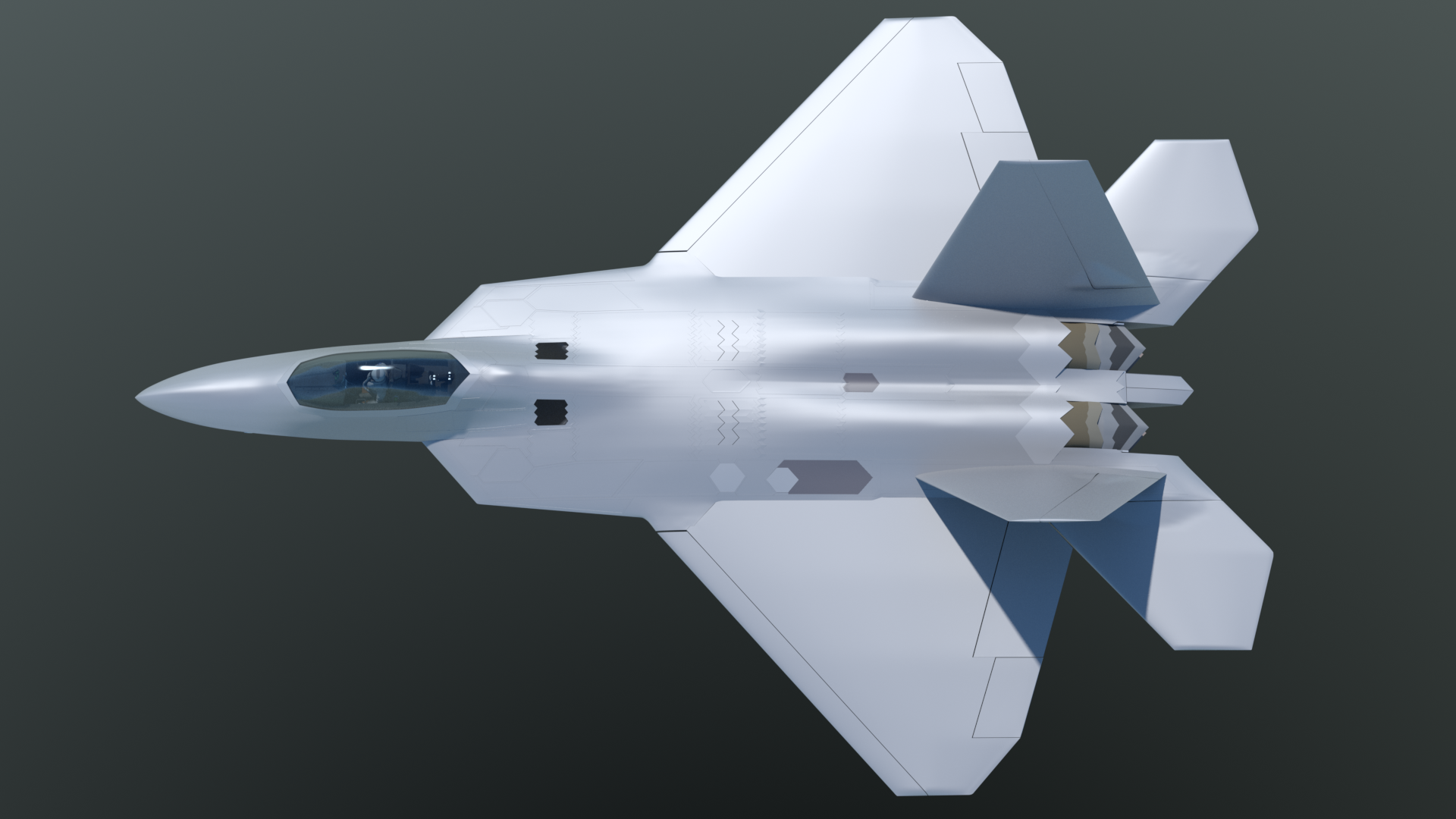
A note on these renders…
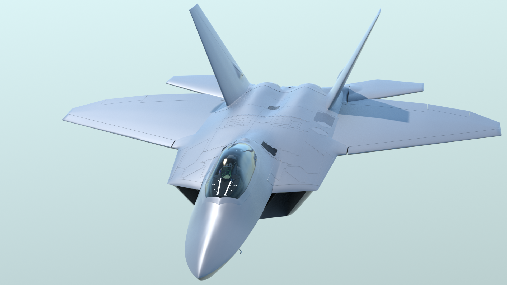
I’m intentionally rendering these under the “worst-case” lighting conditions, meaning that the material is a simple metal, with no textures, and in most of them, the light is always at a glancing angle to make the panels be as visible as possible. It’s working as planned, as you can see in the top view render, where the panels have a much more subtle look.
Adjustments:
I don’t want to bore you with every step, but the process is ongoing. Sometimes I’ll apply several panels, and then when I get to a later one, it becomes obvious that some of the earlier ones need to be adjusted. After all, I’m doing this based on photos, and not orthographic “blueprints”. Still, it’s really gratifying to see the progress.
You can also see that sometimes, specific edges need to be adjusted, to balance out the look of edge-weighting versus the smooth underlying shapes. Using this sort of metal material at this stage is really helpful to point those things out. It just takes a little patience, and the results are worth the effort.
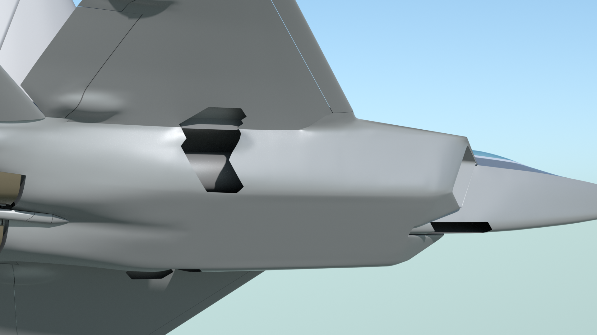
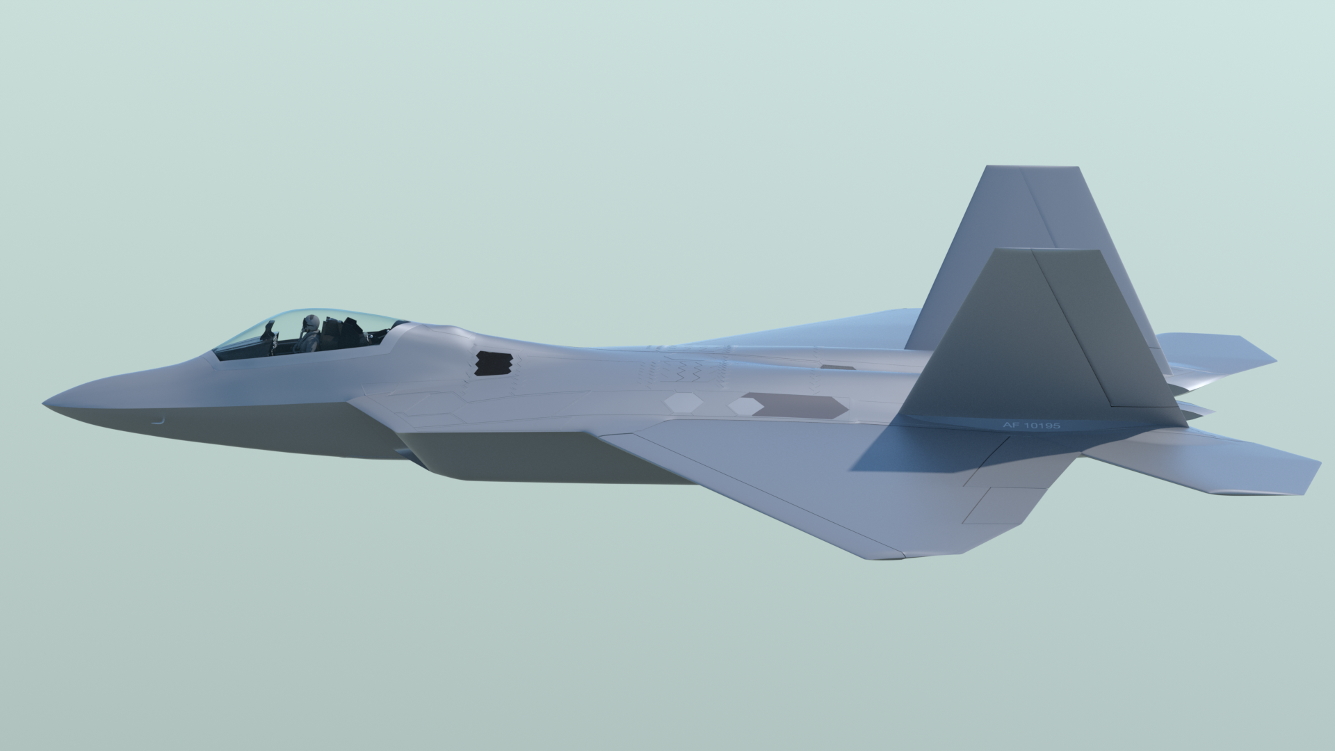
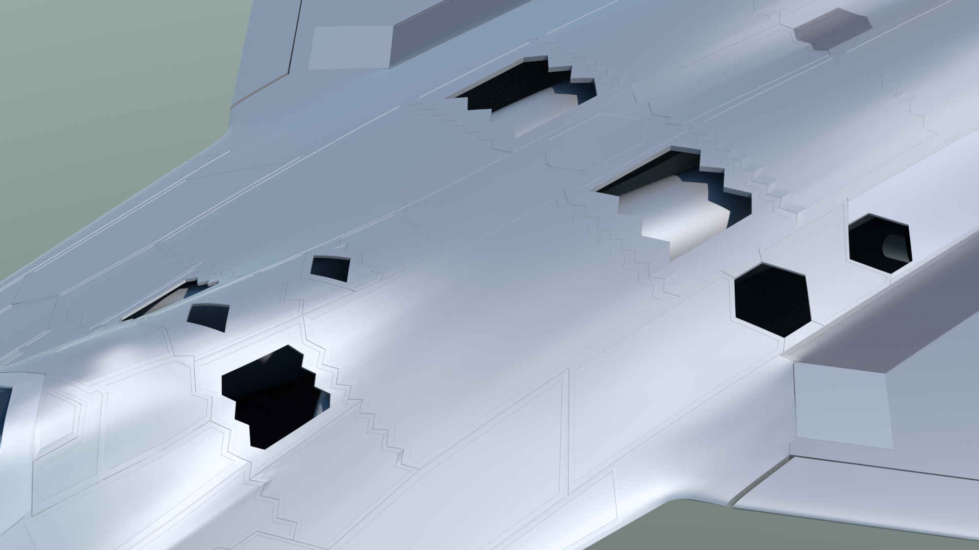
The first render shows this kind of adjustment made to the wing joint area, so the panel edges would be flush. (the dark-colored panels)
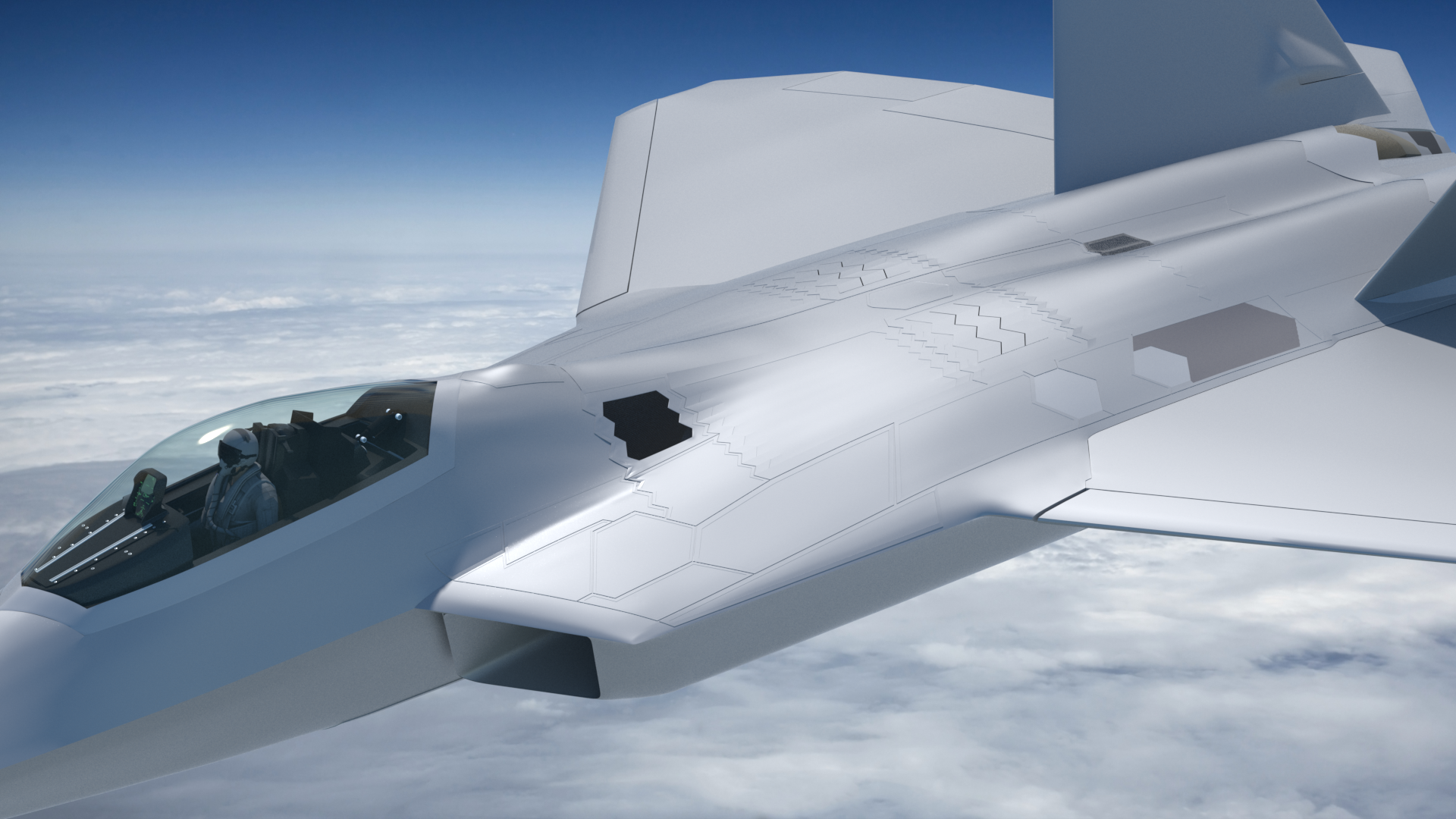
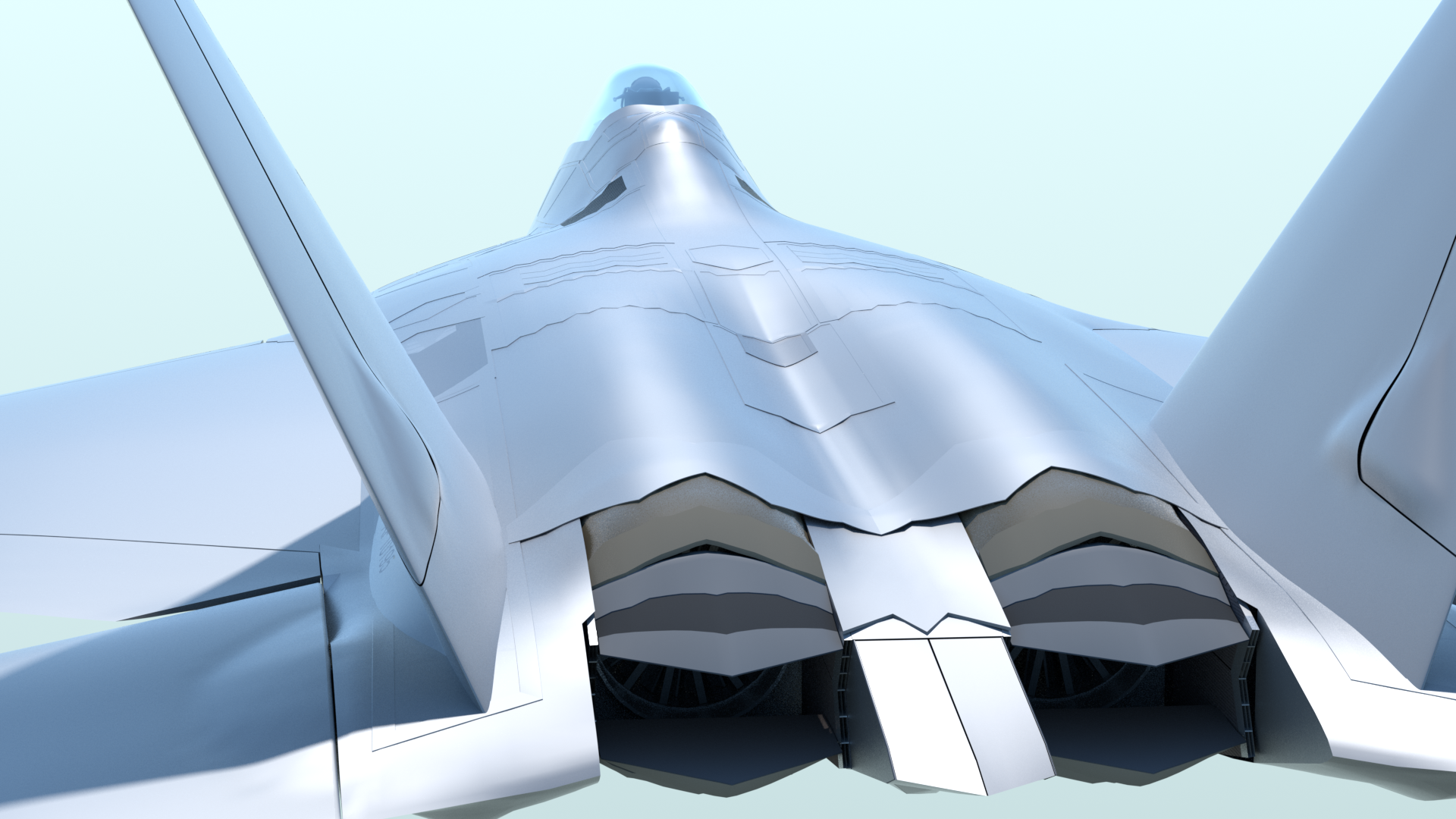
In this render, you can see that where panels will have equipment under them, or where the panels (or doors) themselves will be animated, I’ve removed the underlying fuselage skin.
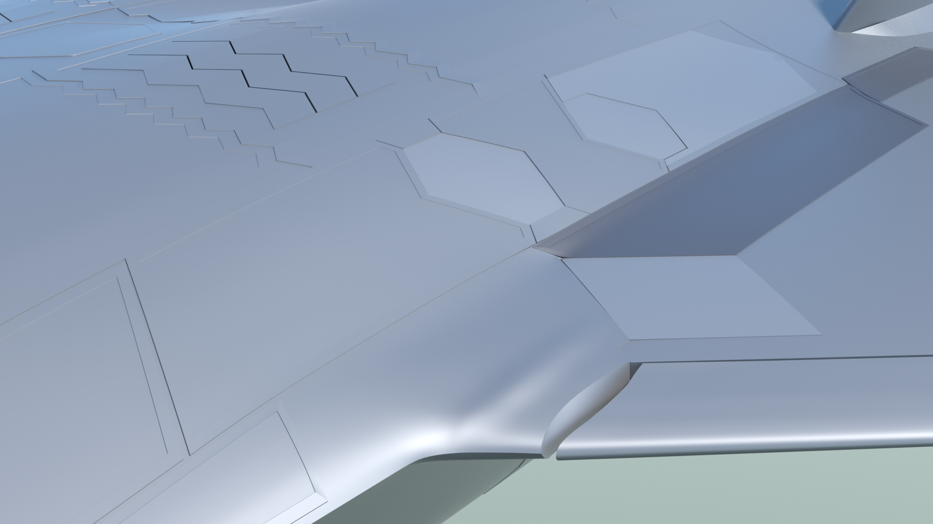
Starting on the inboard bevels on the leading edge flap (top and bottom) and the small bulge for the actuator, just inboard of that.
Next, I added the doors and vent for the gun port on the right side of the fuselage. This marks the stage in building where the fuselage is no longer left/right symmetrical.
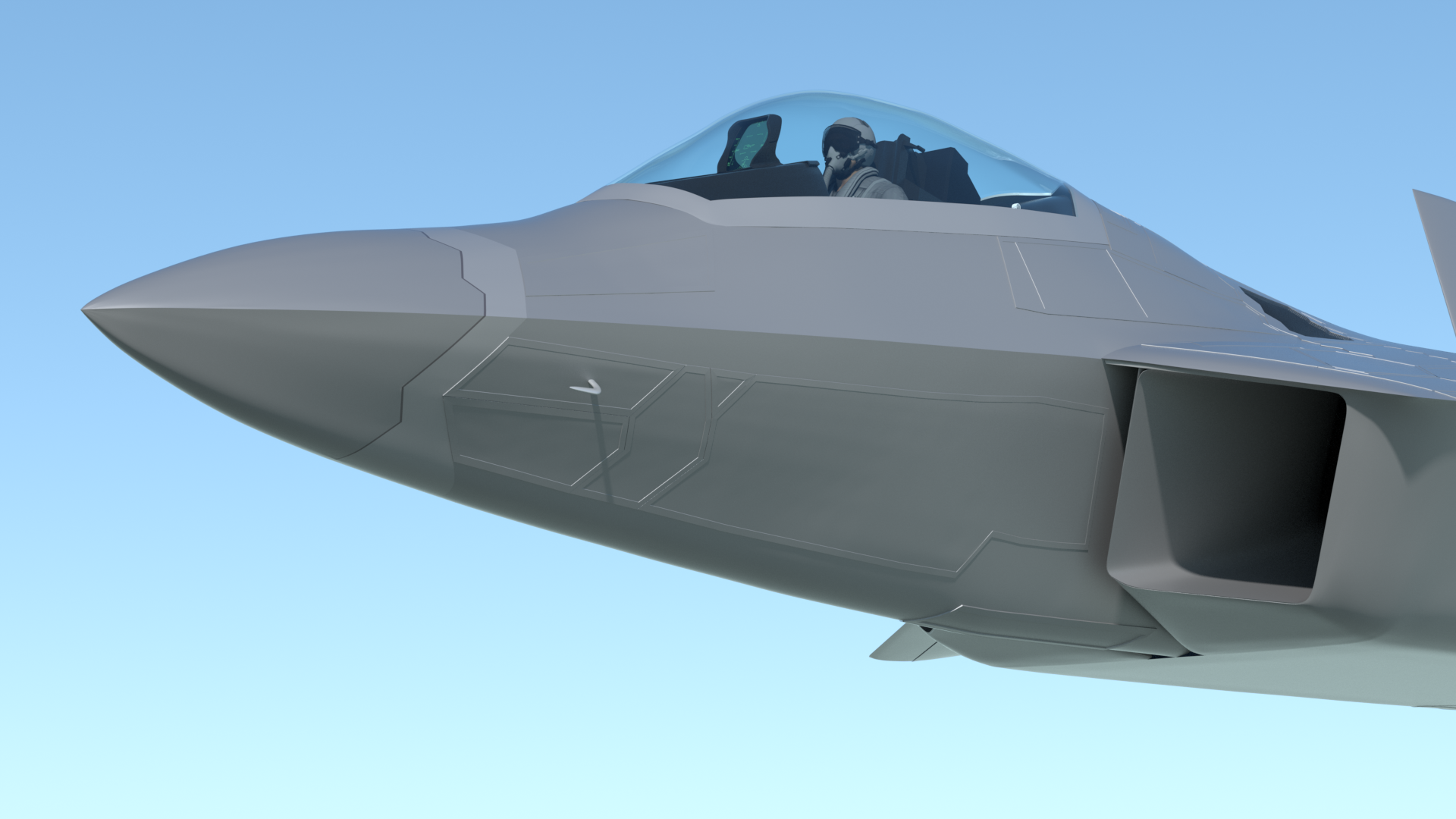
Below - This image shows the separation cuts have been made for the nose cone, (or "radome") as well as the addition of more panels on the nose. (still more to add in that area)
Follow-up on the external panels:
I've been quite happy with the method outlined above, for creating the external panels. You'll notice, however, in later renders, that I ultimately reduced their "elevation" or "thickness", as the model progressed, to make them look slightly less pronounced. The results I've achieved in the later pages look more realistic, as a result.
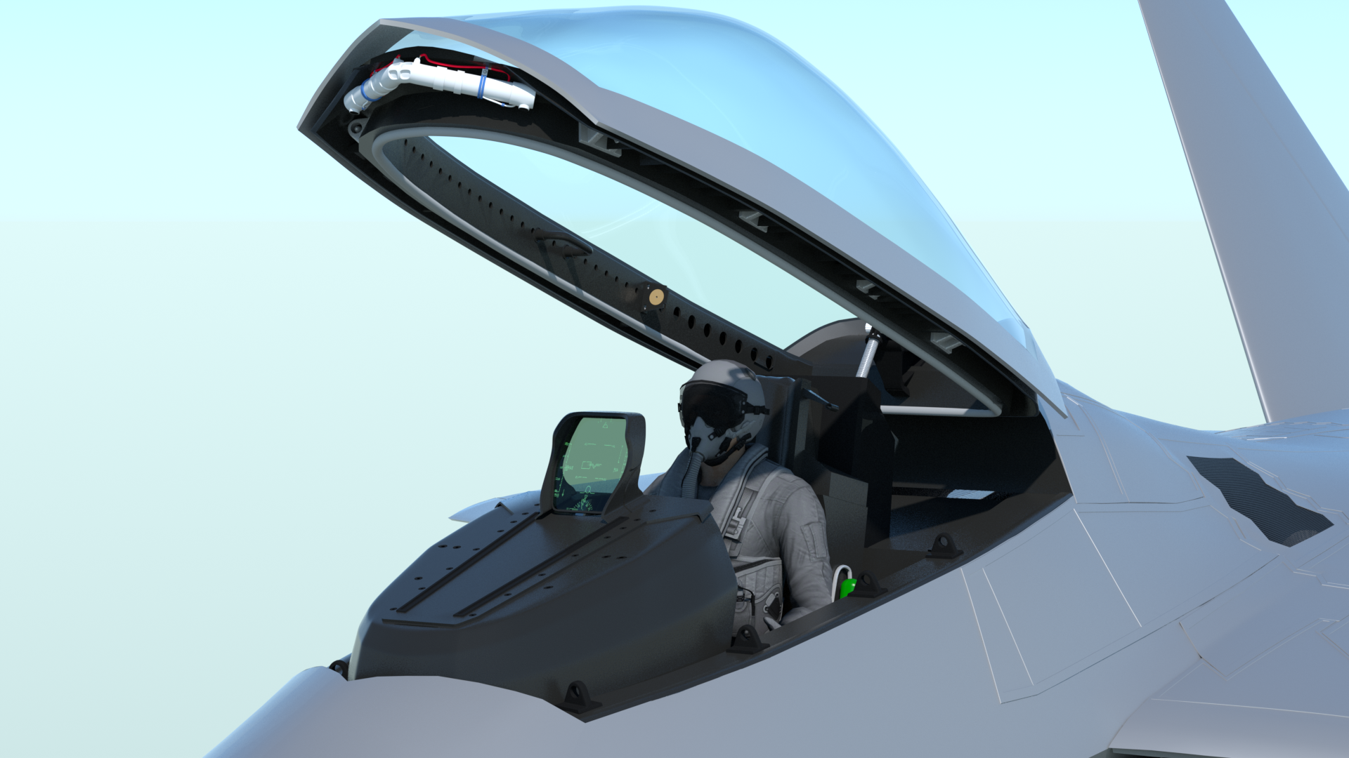
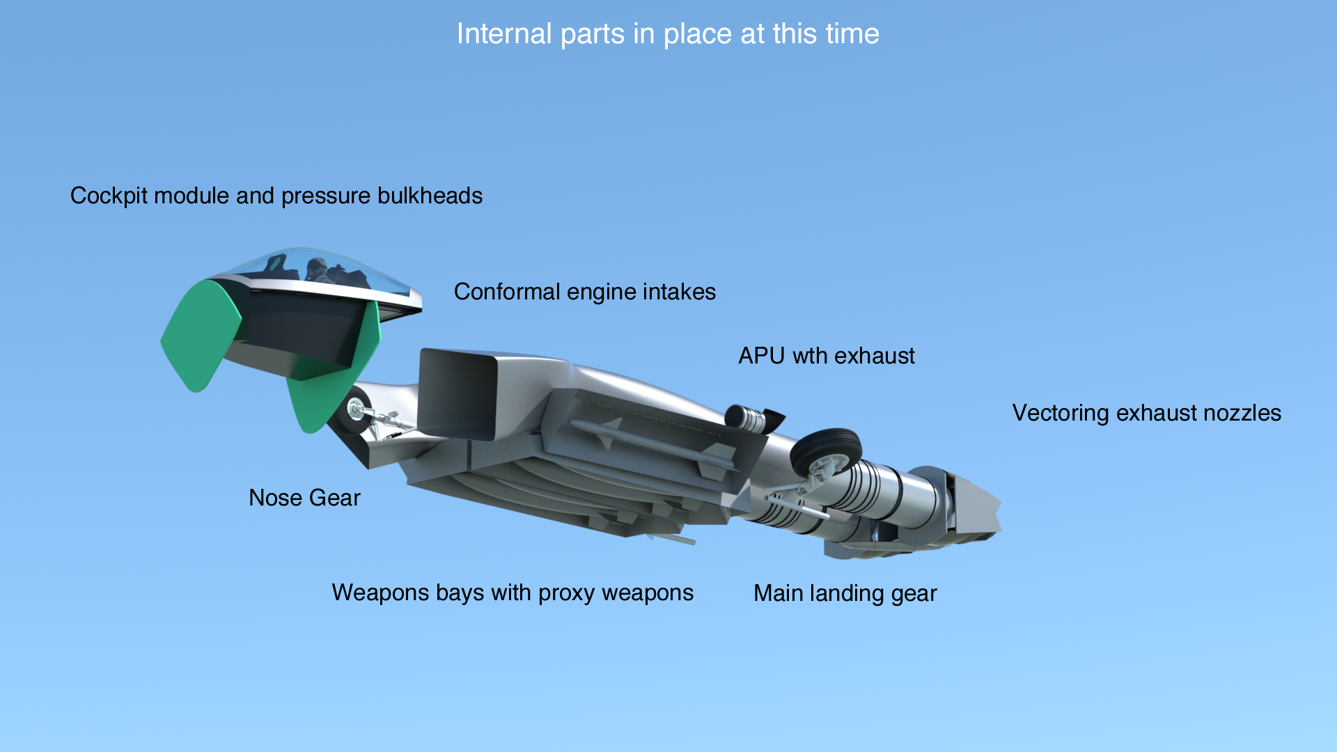
Internal parts:
Once the exterior airframe is nearly complete, I'll be adding as many structural items and other equipment to the interior as I can document. Here is what's inside, at this time... just the basics.
Click the "Page 06" link below, to continue.