A change in plans...
The original plan for this project was for the customer to use the former patterns to build male plugs by hand, which in turn would be used to create female molds. With the procurement of some better (factory) drawings, the customer now decided that it would save them a lot of fabrication work to directly machine many of these parts, rather than using the formers to build the plugs by hand. I used the "Power SubD-NURBS" plug-in for MODO, which allows me to convert sub-d models to several machine-ready formats.
There's just one problem... In the interest of moving quickly for this customer, I often froze the sub-d parts to hard polygons, so that I could freely use boolean cutters. One of the requirements for using the plug-in mentioned above is that the parts must be sub-d. Additionally, some parts had to be altered to match the new drawings, and some parts had to be completely rebuilt, but hey... That's life. Luckily, I always save the original sub-d parts as a project proceeds, so it wasn't like starting over completely.
Differences in techniques for machining:
The methods I had been using for creating images and animation from this model were valid and fast. But, for machining, there are some new considerations. For example, all openings have to be closed up for machining. So the exhaust area of the fuselage, the base of the canopy, the interior of the jet intakes, the roots and tips of all control surfaces, and both ends of the turbine ducts have to be closed. Any small overlaps, such as the fairings around the tail surfaces, now have to be refined and/or connected, to be made machine-ready. A vital question was whether or not the machining would tolerate "intersecting geometry". For example, the wing fairings that I simply stuck onto the sides of the fuselage worked fine for images and animation. But, would the machine be able to cut the fuselage and the fairings as though they were a single object? As it turns out, that's just fine... another huge relief, because otherwise, these parts would have to be connected, and their polygon flows were radically different.
This makes the parts somewhat less suitable for images, but that's not the focus now. And, as mentioned above, all the parts have to be sub-d. So, any parts previously modeled in hard poly mode have to be converted, or remodeled. Finally, all the parts have to be "export tested". In other words, even though the parts look fine when rendered, I have to export each one in the machine-ready format, and ensure that the sharp edges, in particular, translate properly. Experimenting with various output formats showed me (thankfully) that the same techniques seemed to work for all export formats. (IGES, STEP, SAT, and 3DM) I was able to quickly develop a consistent method for prepping the parts, within days of starting the process, which was a huge relief. The most effective results were to use a combination of Pixar sub-d's ("Psubs") along with edge-weighting. I'll outline this in more detail in a future tutorial for my fellow MODO artists.
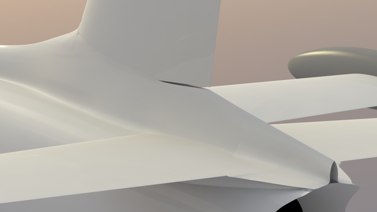
Below: As one example of part preparation - The fairings that surround the tail surfaces have tiny overlaps, which was irrelevant in the image-based planning for this model. But for machining, these parts have to be connected, or moved to a separate (plug) part.
The canopy and cockpit area
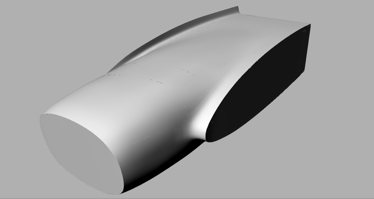
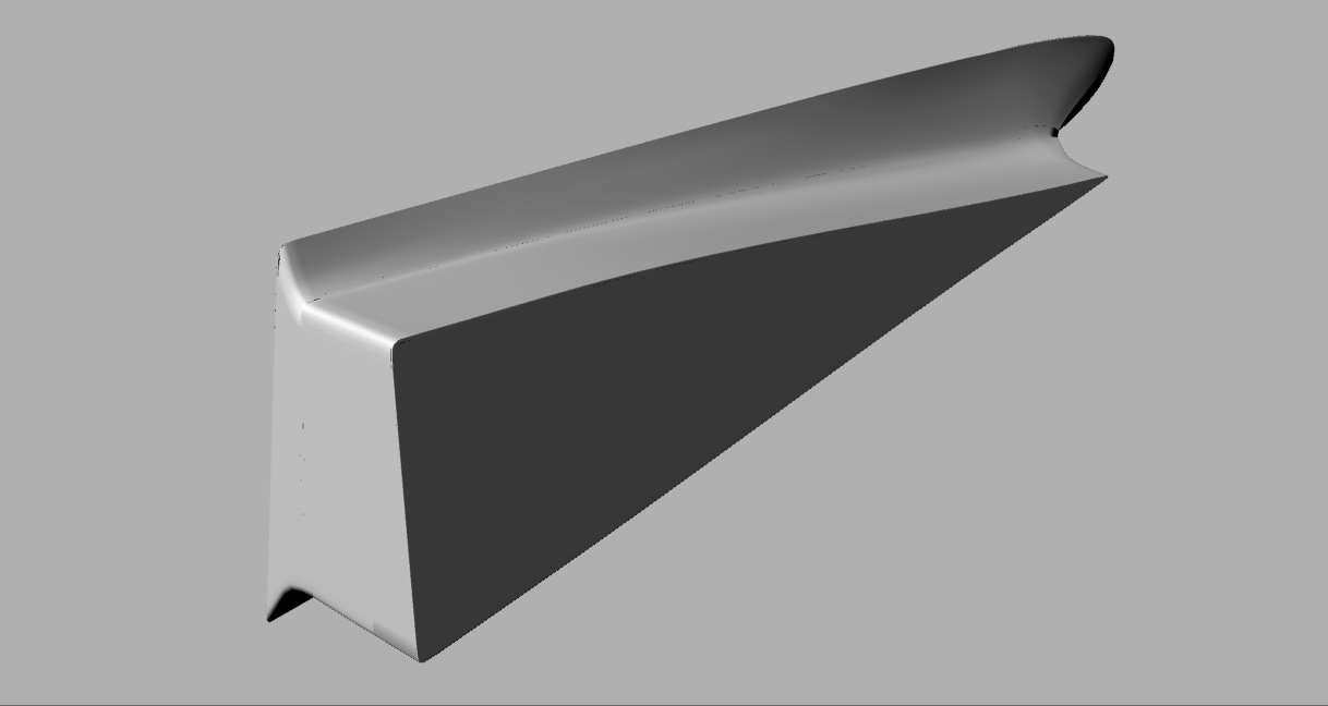
For previous image-based purposes, the two parts of the canopy were modeled separately. For machining, these parts had to be connected, and then a "floor" added, so it would be a solid.
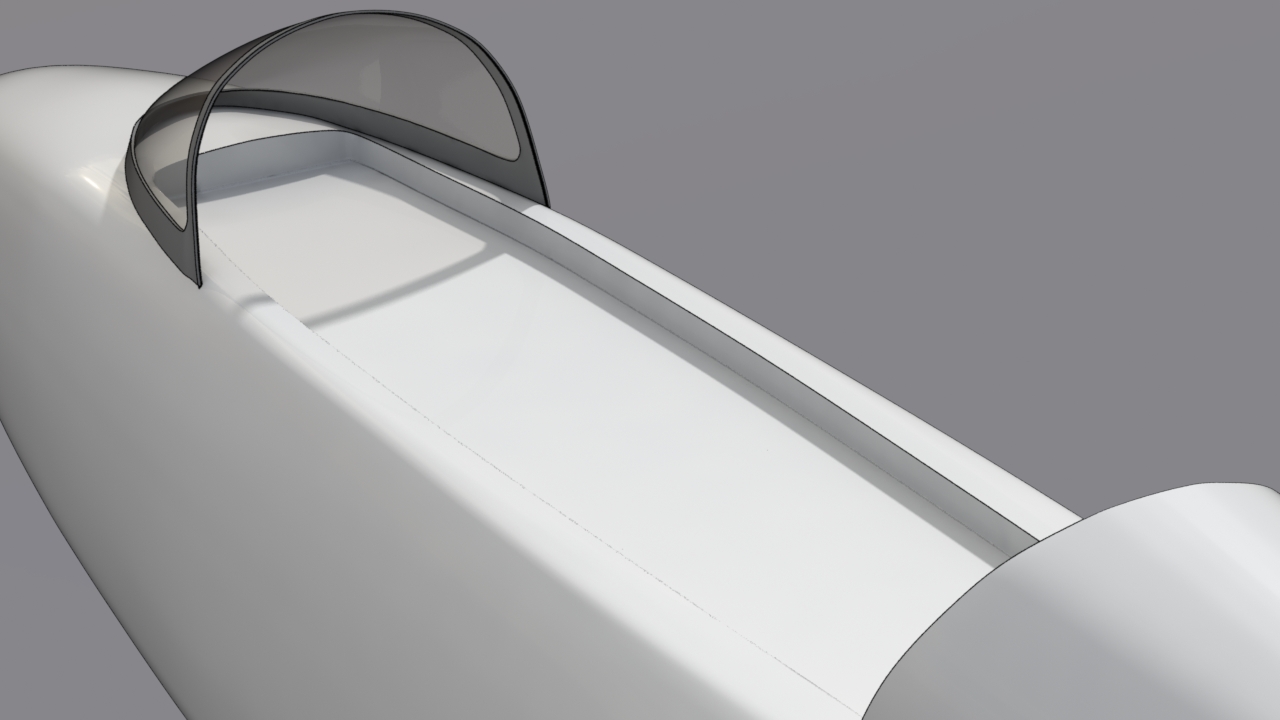
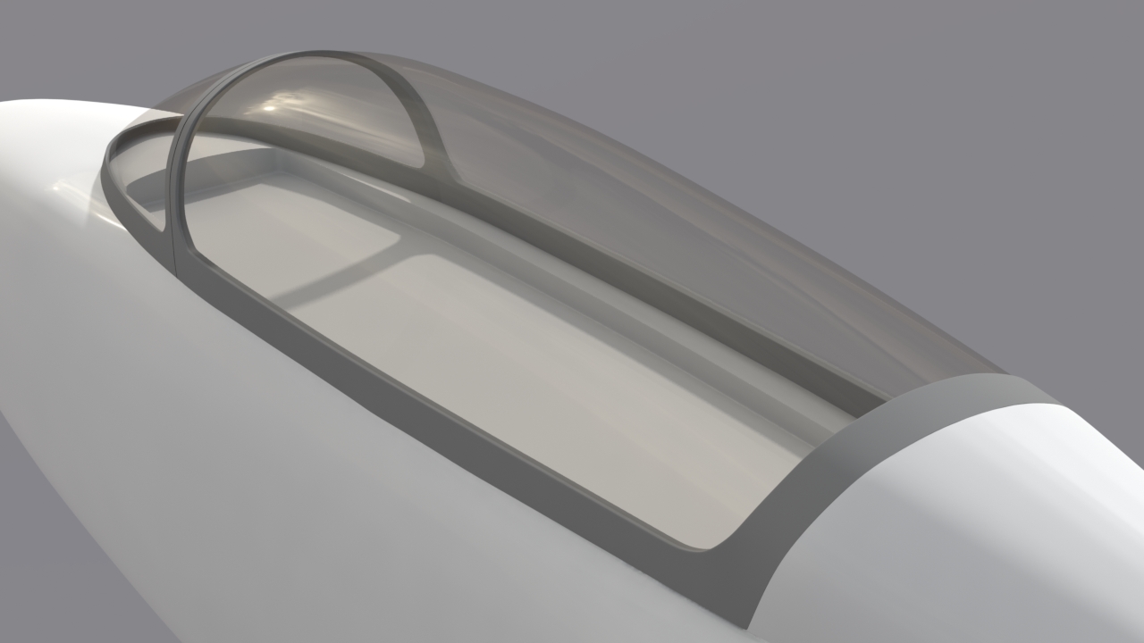
Below, here's the result, showing the IGES file, rendered in Rhino. I've left a tiny edge visible between the forward and aft canopy frame sections, to indicate a cutting line, which the fabricator can use, once the part is molded.
Below, a "fly-around" movie, using highly-reflective materials, to provide a critical look at the surface smoothness.
Internal parts:
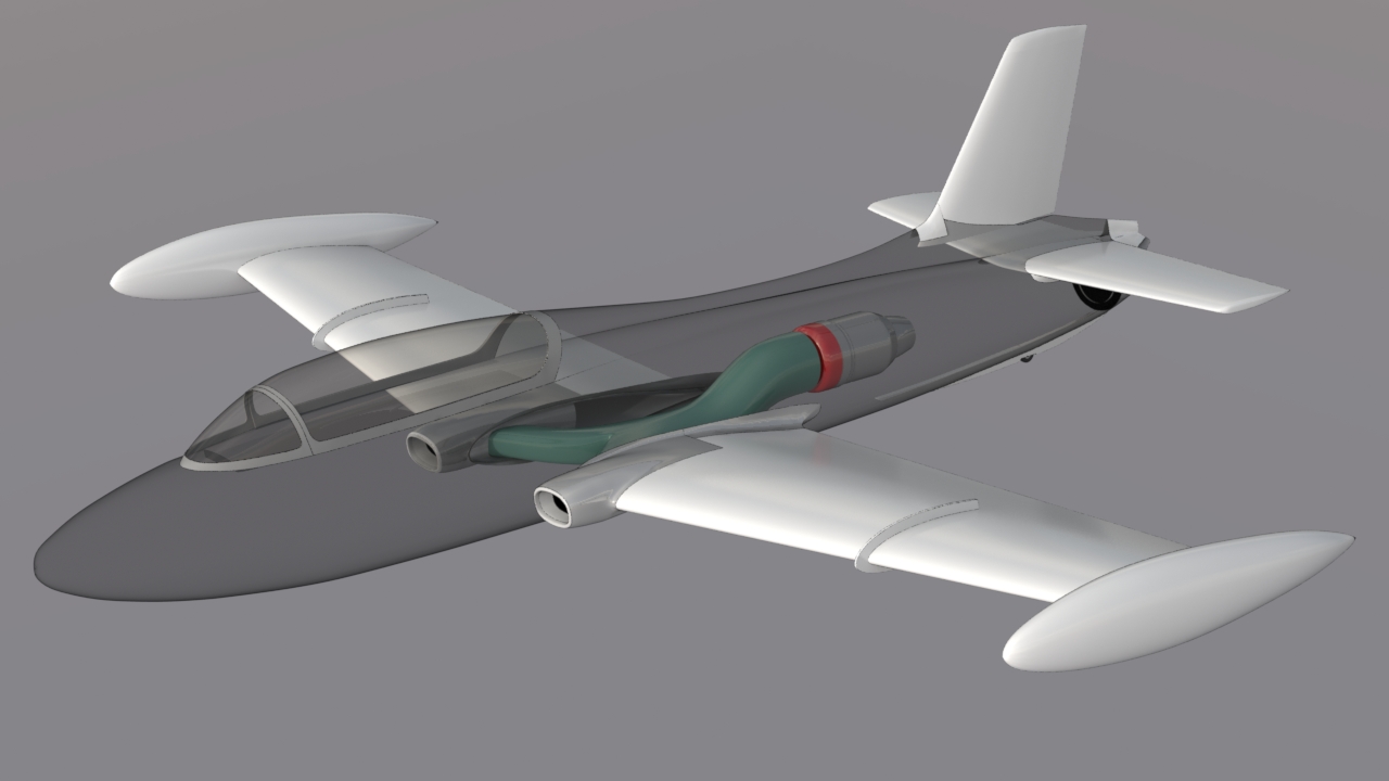
The vertical red cylinder in the image below represents the location of this aircraft's center of gravity. Since the fuel tank would ideally be located there, we modified the turbine ducts to maximize the space around the tank, by moving the ducts toward the bottom of the fuselage.
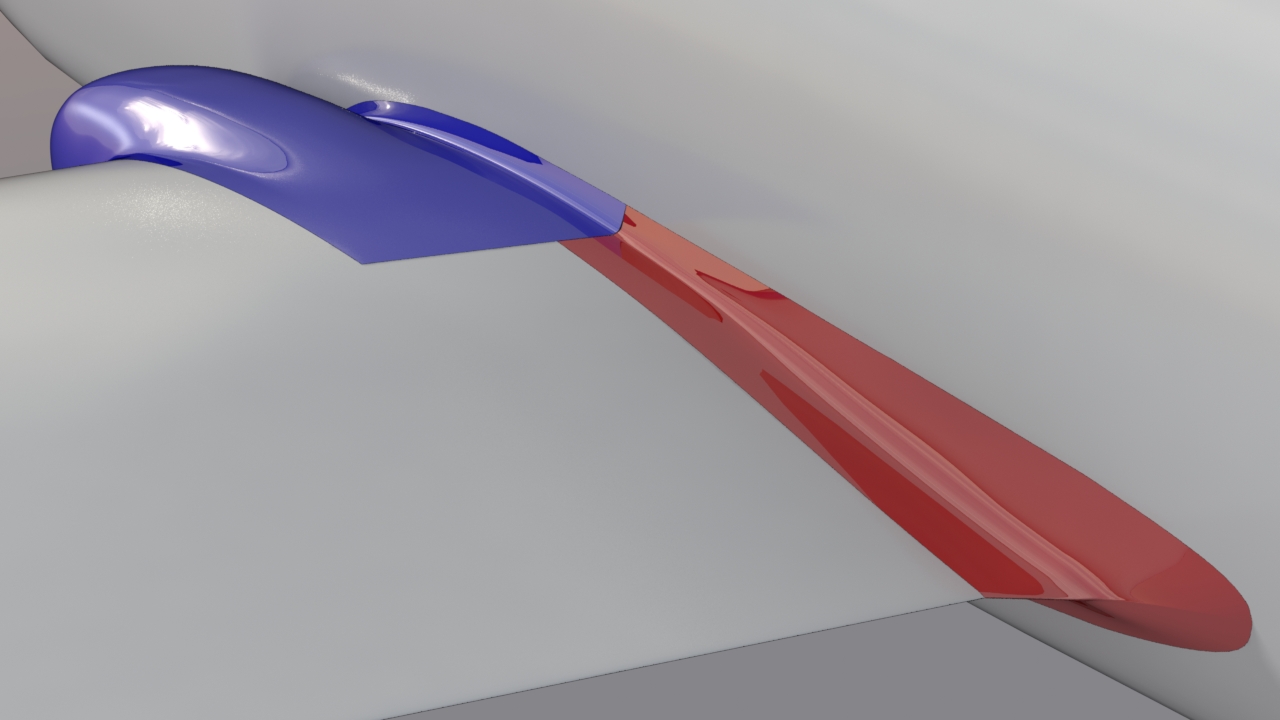
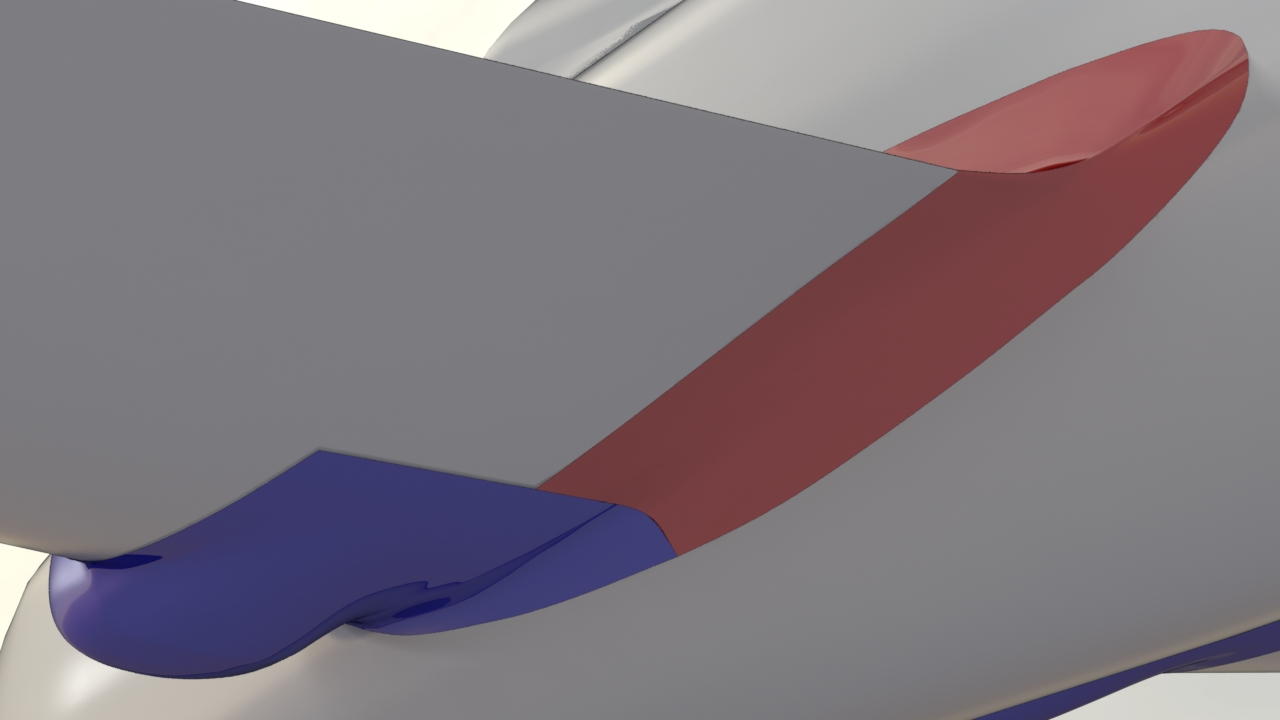
Fairings:
The inlet and fuselage/wing fairings are color-coded here, to make it obvious where the split is. Later, these were split further, along the Z axis, so that part of the fairings could be machined with the fuselage, while the remainder could be separately attached to the wings.
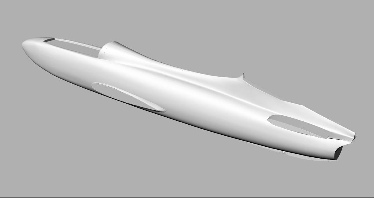
Here, the fairings have been split, and you can see the parts that are molded into the fuselage. (IGES file, rendered in Rhino)
The engine nacelle, with it's integral fairings, are created as a separate plug. (IGES file, rendered in Rhino)
The remaining (aft) portion of the wing/fuselage fairings was separated into it's own plug too. (IGES file, rendered in Rhino)
Thoughts on plugs and molds:
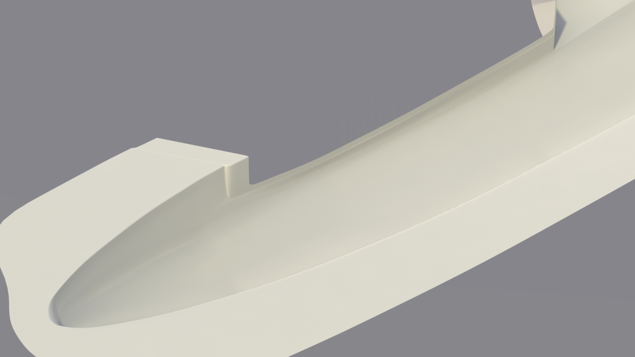
Years ago, I used to build a lot of plugs and molds. (See my archive site at NextCraft.com) That experience helped me recognize that although what I had modeled in the cockpit area was fine visually, it wouldn't work properly in a left/right molding procedure. I constructed a mold proxy to point this out to the customer, and also pointed out why it's important to have a couple of openings in the mold halves, to provide the ability to seal the seam, during fabrication. In this case, those openings were in the cockpit area, and the exhaust area of the tail.
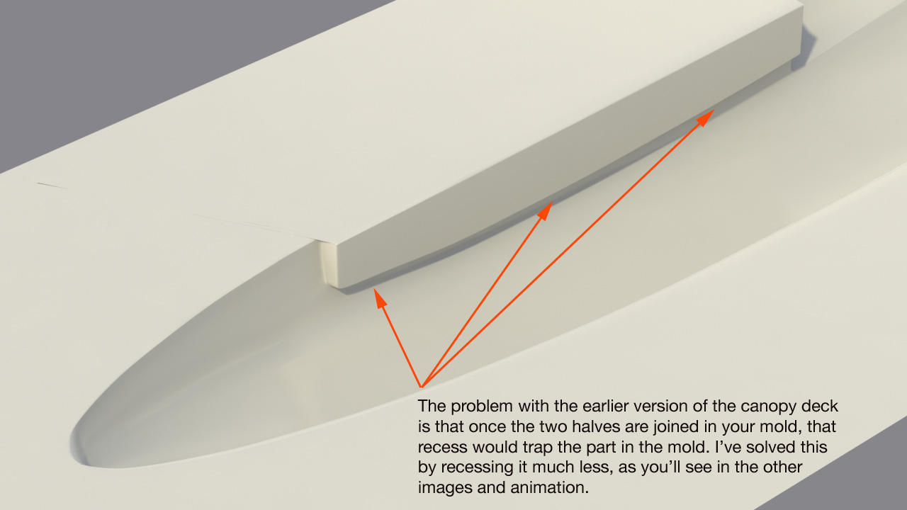
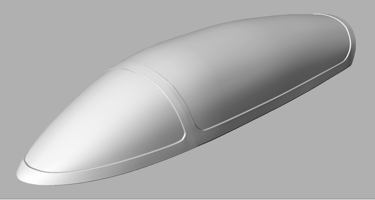
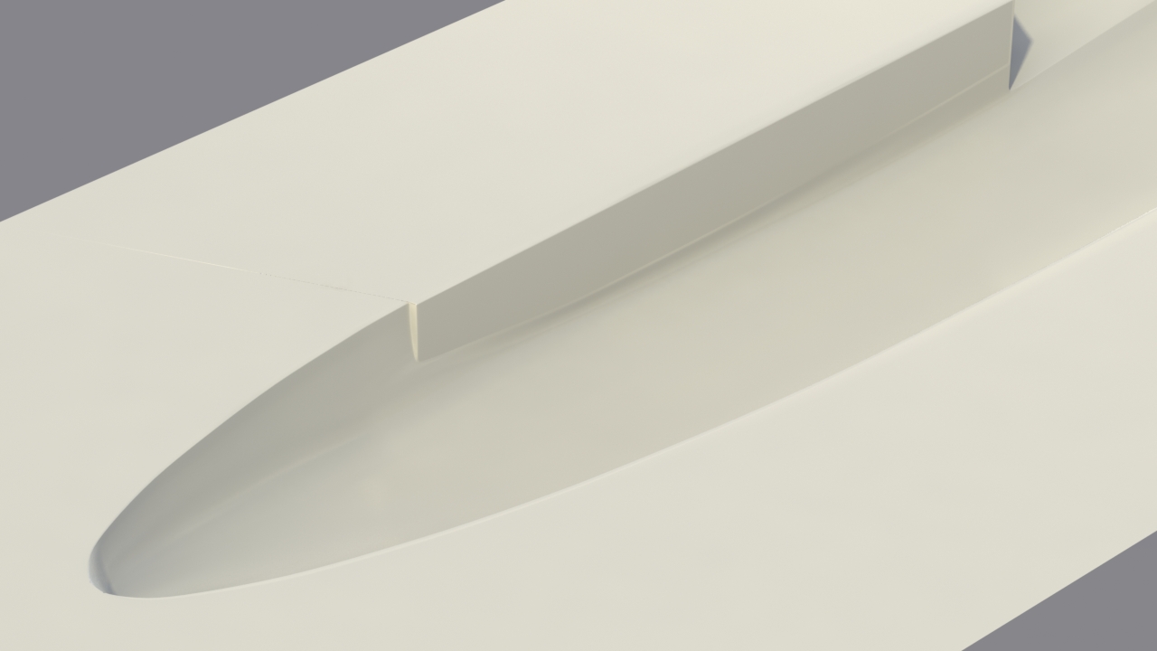
Below - The depression in the cockpit area has been made more shallow.
Below - Showing an area I recommend removing, to allow access to the mold interior.
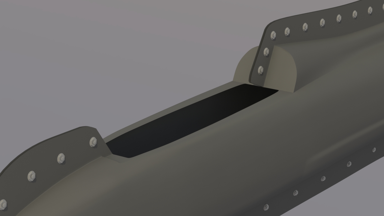
Below - A mockup of the two mold halves bolted together for fabrication.
Click the "Page 05" link below, to continue.