Shaping the Boeing 787-8 "Dreamliner"
Changed my mind about doing the windows next. This is a sub-d model, so I think I'll wait until I'm more comfortable with the fuselage shape, then "freeze" the geometry to polygons, before making those kind of detail changes. In the meantime, there's plenty of other stuff to do.
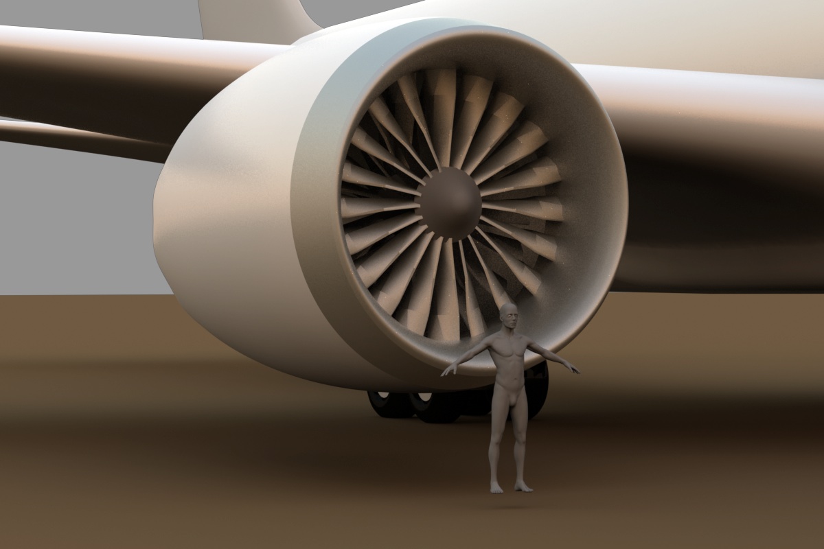
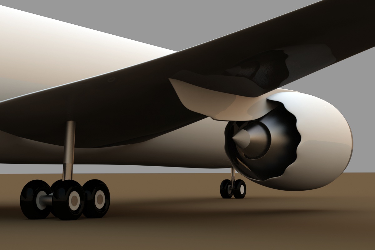
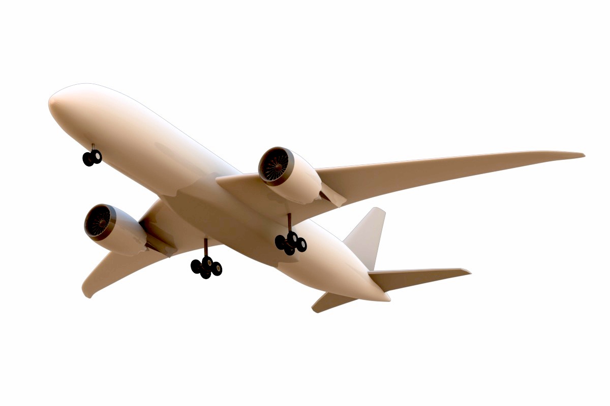
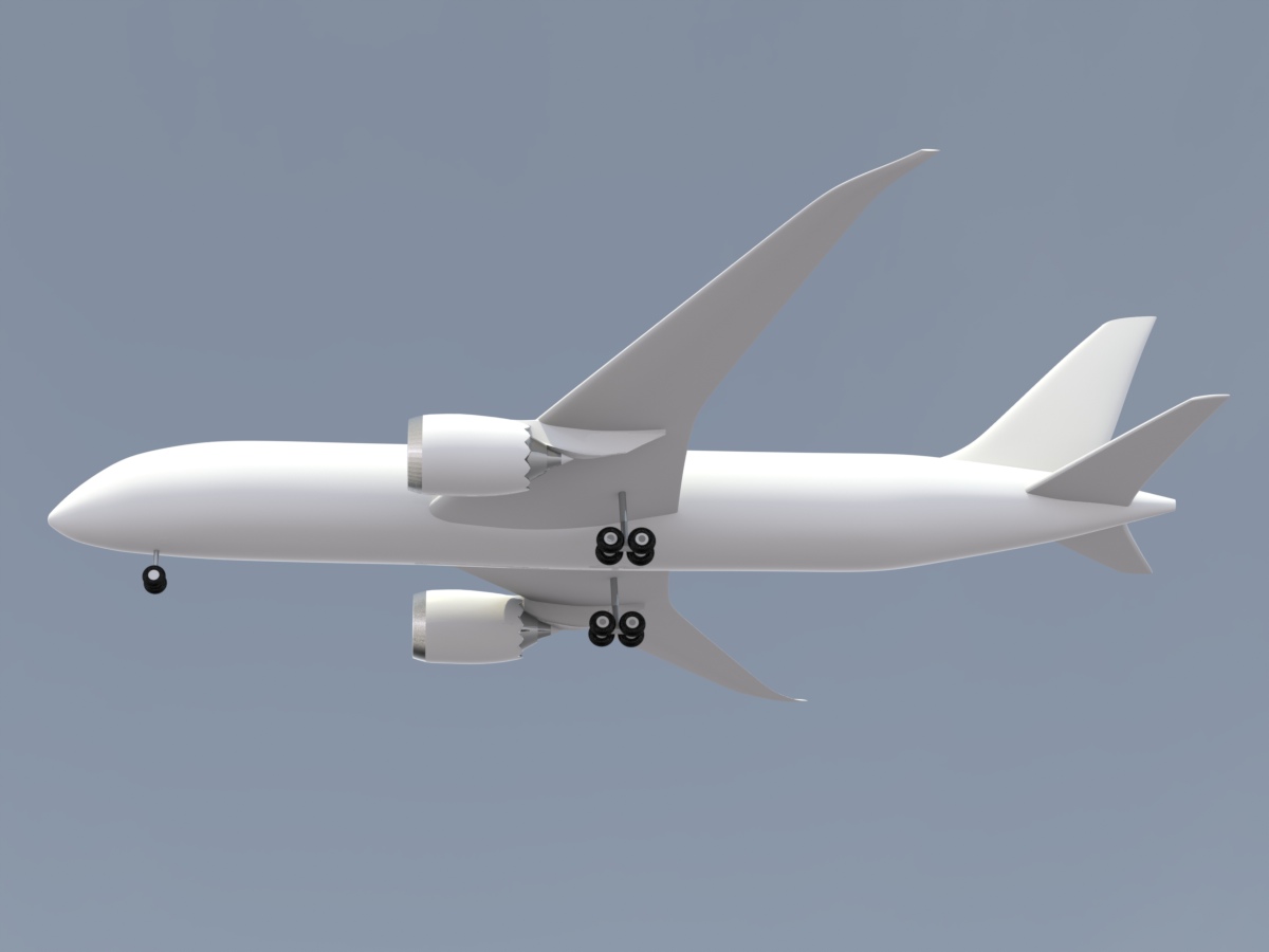
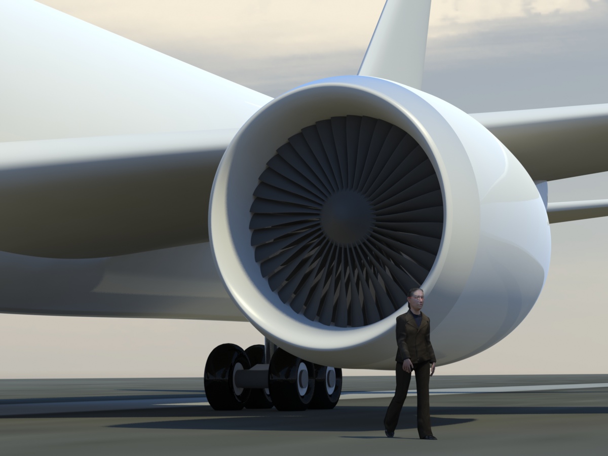
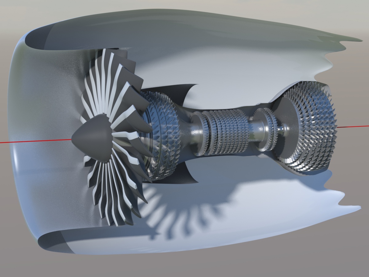
Spent some time on the engines. There are two large fans, and an internal liner, which gives a pretty convincing effect, even when looking directly into the engines. I also rounded the intake lip on the nacelle more. You may notice an error in this image… Half of the front fan blades are reversed. As soon as I caught that, I fixed it. (See below)
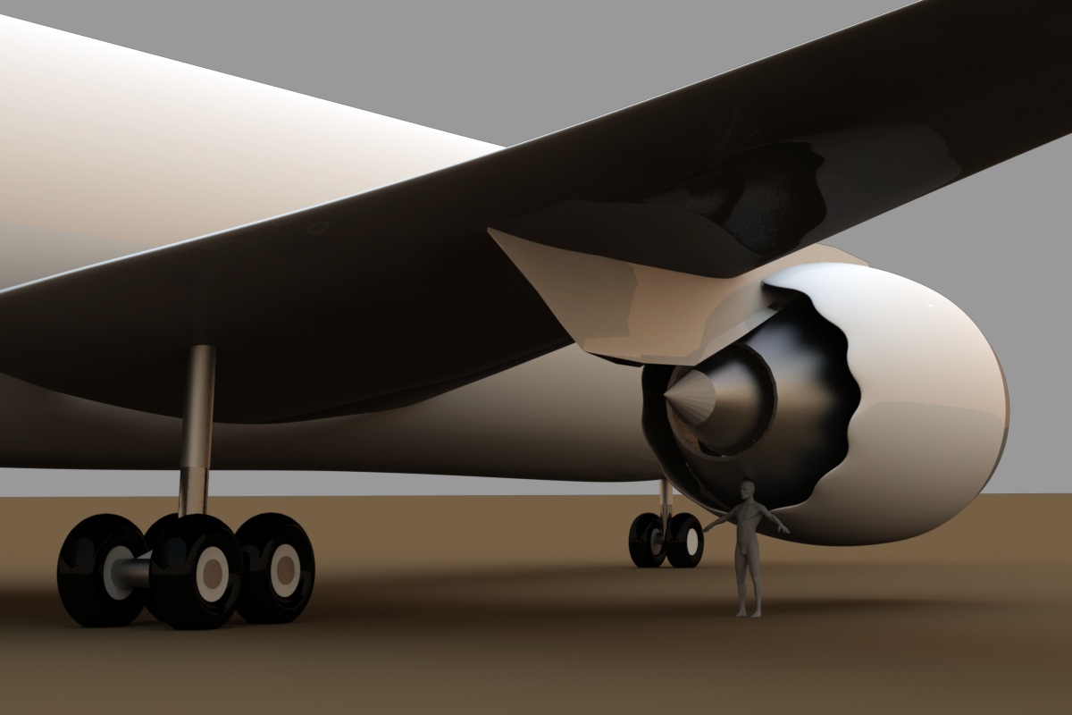
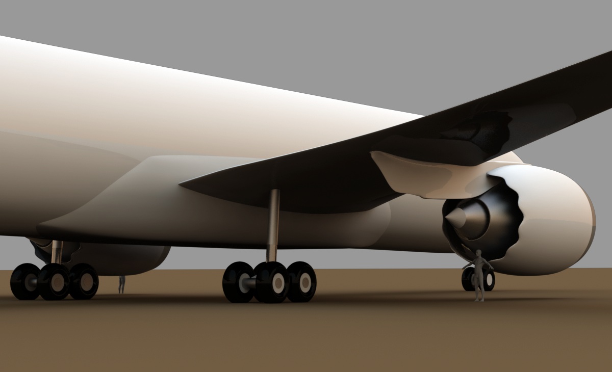
I'm working on the engine mount, which is connected through the nacelle, and into the wing. I don't have good photos of this area right now, so it's not "final" yet. You can see in this image and the next ones that I'm also working on the wing fairing. This is just a normal fairing on the upper part of the wing, but on the bottom, also serves as the main landing gear well.
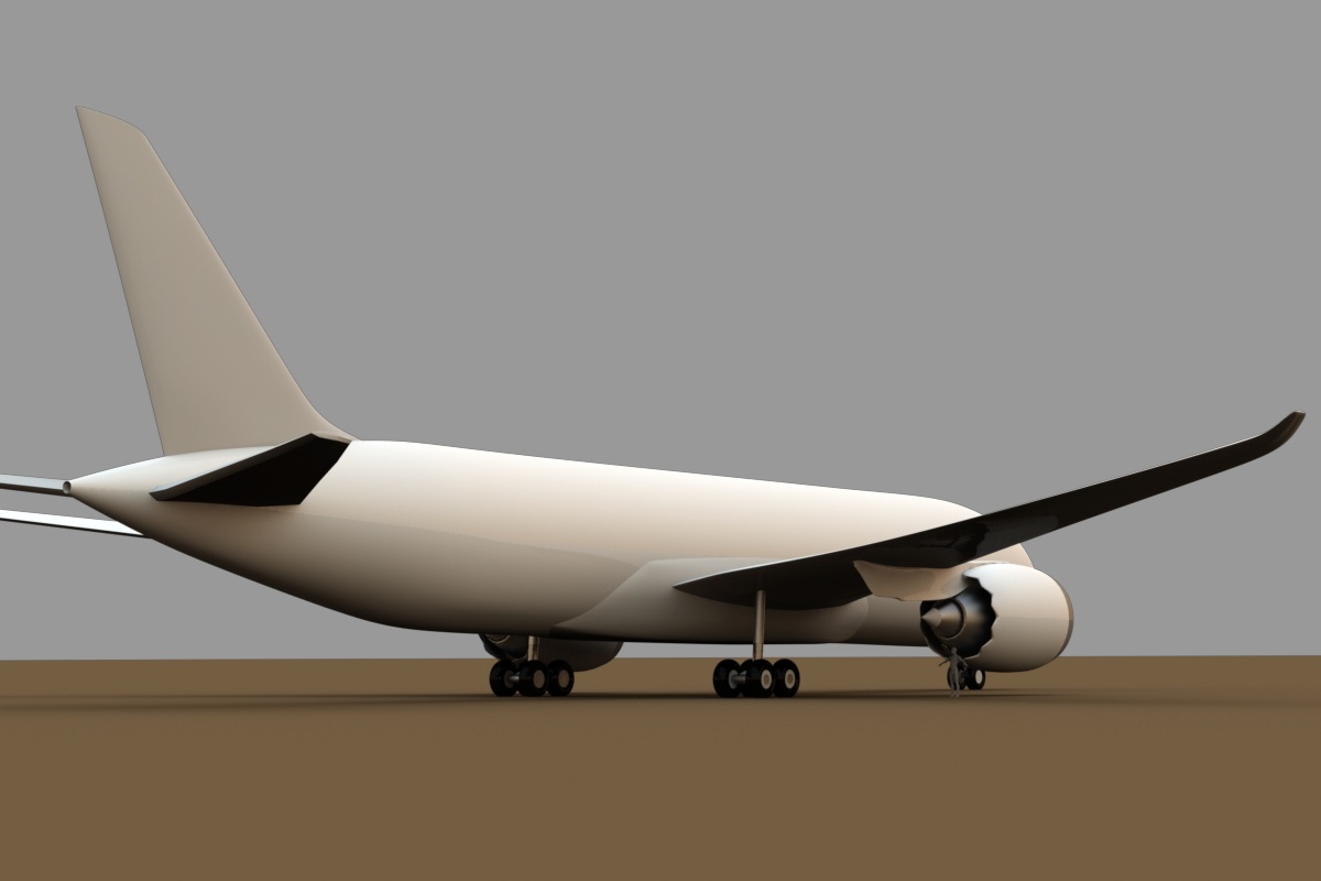
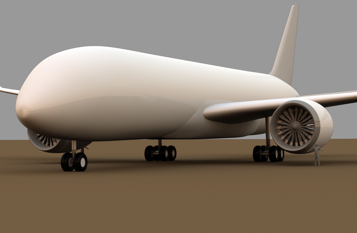
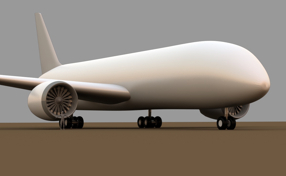
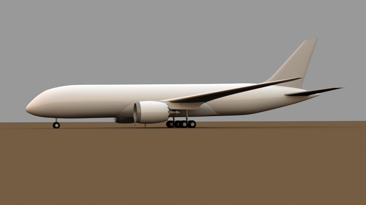
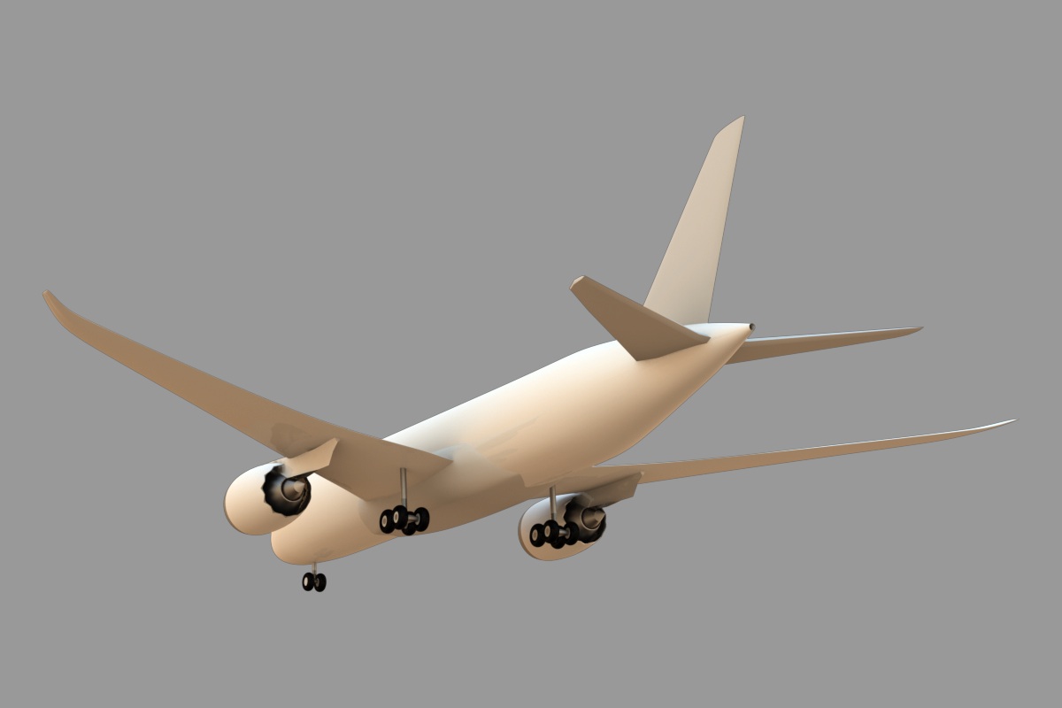
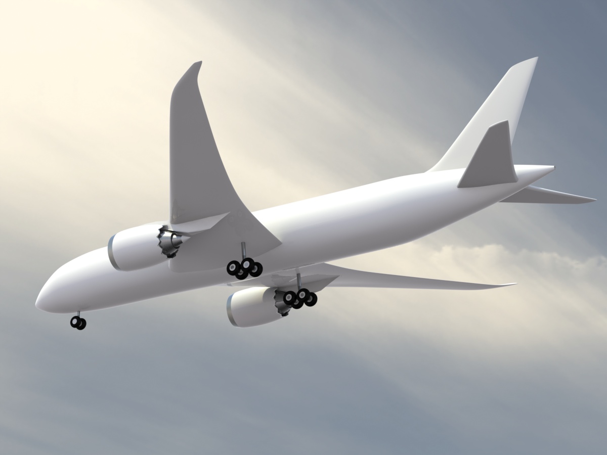
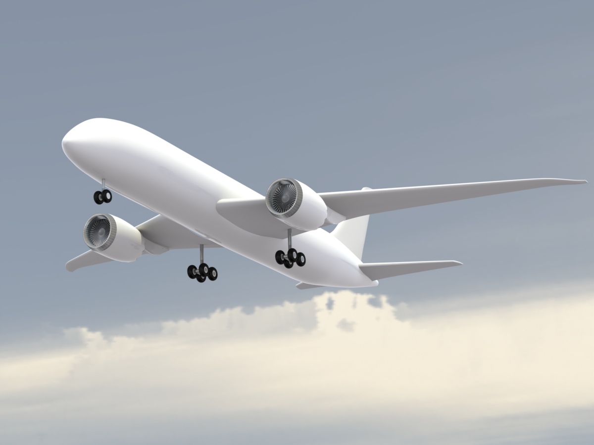
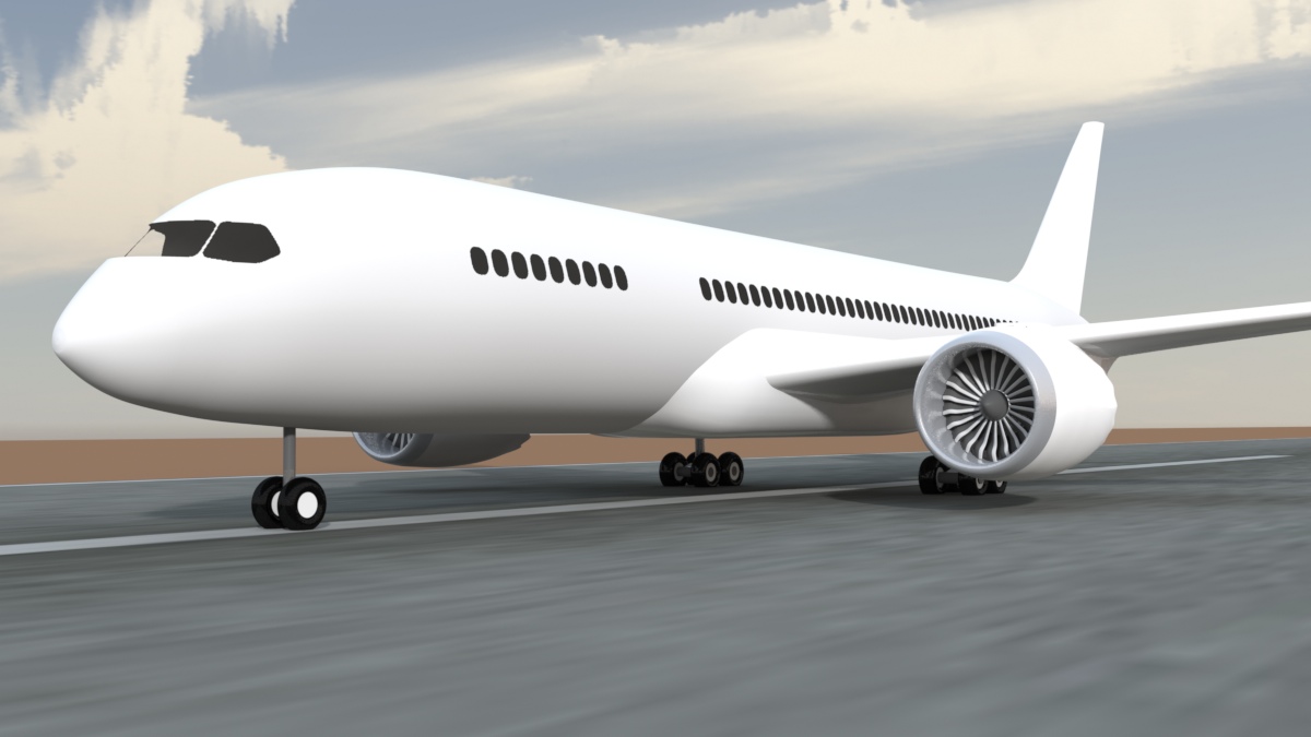
These next three images just show the overall shape, which I'm very happy with, considering how quickly it came together. I actually rebuilt the vertical and horizontal tail parts to be more accurate, because it was so easy.
I abandoned this project for some time (in December, 2008) due to lack of documentation. Now, the aircraft has made it's maiden flights, and my documentation file is growing. So, I'm back to this project, beginning again in June, 2010, and will be completing it.
I've rebuilt the wings completely, made various corrections to the tail surfaces, landing gear, and engines, and have corrected the fan blades.
Planning the doors and windows
I do a lot of aircraft models, and many of them have something in common. That is, they typically have curved surfaces which require many openings to be cut in them. (windows, doors, and hatches) So, since I have this issue constantly, I've developed a way of dealing with it, providing versatility along the way. This aircraft is a good example, because not only do I need some openings, but I need a LOT of them.
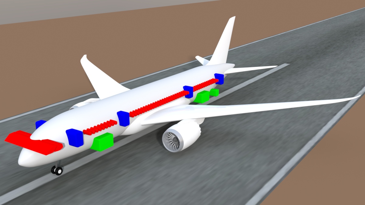
This method is good for both hard poly and sub-d models, because what I'm really creating is a "tool", which can be used in a variety of ways. As you can see in the image below, I've made a lot of "cutter" objects, and color-coded them. (RED for glass, BLUE for cabin doors, and GREEN for cargo doors) I made these objects by tracing over my reference drawings (as backdrop items, in MODO) and then extruding them so they could be used in a boolean. But there's much more you can do with these…
First, I do an orthographic rendering of these cutters, at a large size… say, 4000 pixels wide or larger, to avoid pixelization in later steps. I then use a graphics program like PhotoShop, to create a PNG file that has a transparent background. Make the cutout areas black, to use as a stencil map, or color them, to use as a diffuse map. Examples of both are below.
Below, a small version of the image I used here, with the white color representing the transparent background. Using the aircraft side view drawing, I made sure that I sized the length of this image to match the length and height of the fuselage geometry. That ensures that the image will work with the UV map. This version has grayish windows, and was used as the diffuse map, and another copy was made, which has pure black windows, to use as a stencil map. I was careful to keep antialiasing OFF in PhotoShop, so that the color remains pure.

Here's the diffuse map applied to the fuselage's UV map. I like this one early in the process, because it lets you pre-visualize what you've done, with no effect on the model. It's great, because it's non-destructive, and works with both hard-poly and sub-d models.
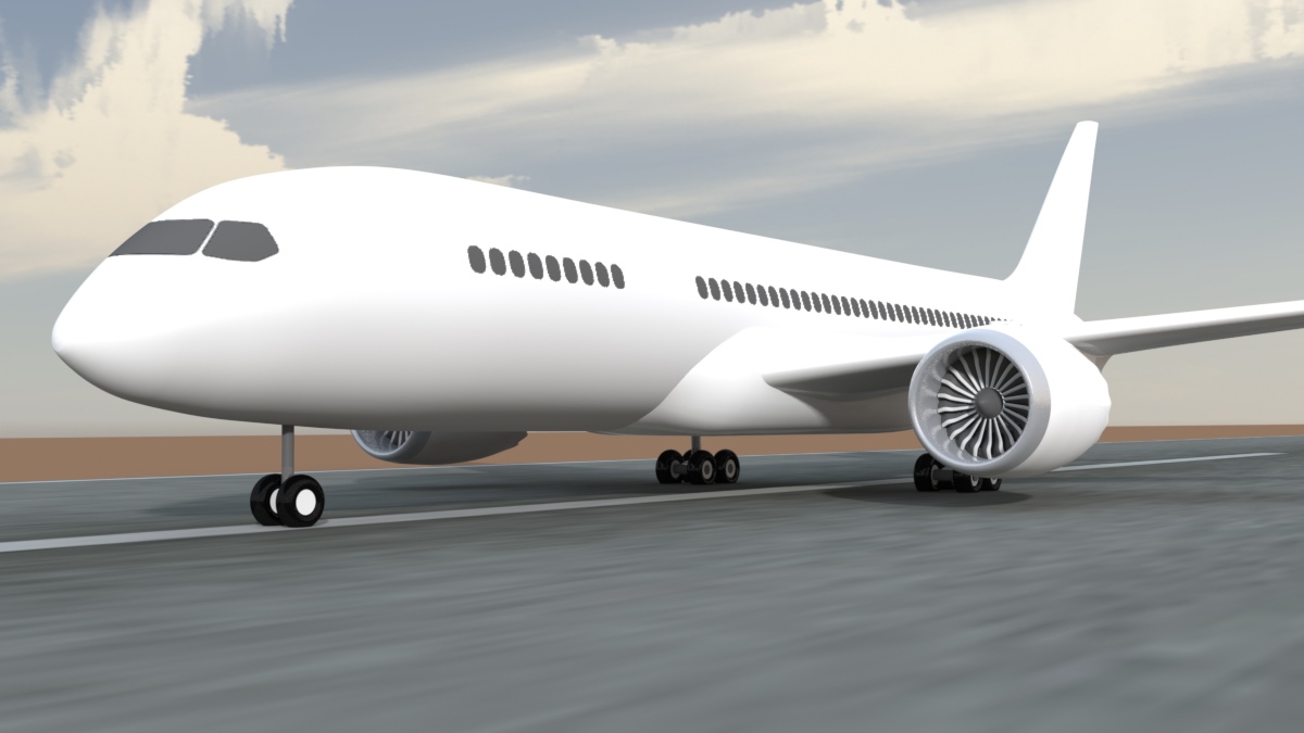
Here's the stencil map applied to the fuselage's UV map. As long as your stencil map is high-resolution enough, this perfectly creates the illusion of cuts in the geometry. Again, it's great, because it's non-destructive, and works with both hard-poly and sub-d models.
But…
My problem with using this method in final models is that it's difficult to build detail around these imaginary cutouts. You can't see them while modeling in MODO, and so you're working "blind", checking it against render previews, etc.. You can see what I mean in the MODO screenshot below… The stencil map effect isn't visible while modeling. (The diffuse map is.) That leads me to the use of booleans for this kind of thing.
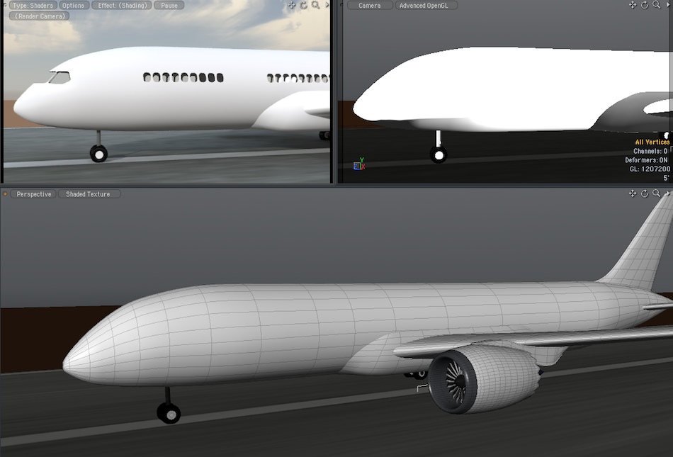
If you've done much sub-d modeling, you know that although you could model this window and door geometry, it would be quite a bit of work to keep the mesh right. You could, for example, leave the diffuse map on, while you're modeling in sub-d, to use as a guide, but it still would be difficult. So, my usual method is to very carefully make sure that the shape is the way I want it, then freeze the geometry. Once the geometry is frozen, those cutters can be used to make all the openings with a boolean operation. I recommend MODO's "stencil" option for this, because that leaves the cut-out polys in place, and MODO also places the "Default" shader on those polys. Save them, to make the windows and doors, and they will fit perfectly!
The engines
I've decided to model the General Electric "GEnx" high-bypass turbofan engines used on the 787, and found some great information on the GE site. I've got a long way to go, but here's my start on the main components. In this case, I'm working from the inside, out, so I've assembled the main drive shaft, bypass turbines, compressor turbines, pre-mix turbines, and combustion turbines, along with parts of the case, and the bypass shroud.
Good News!
When I started researching turbofans, I collected everything I could on my own, and then wrote to three manufacturers that all make these large engines, I was most interested in the GE engine, so I wrote to General Electric first. But I also wrote to both Rolls-Royce and Pratt and Whitney, in case I couldn't get more info from GE. So far, (ironically) the only one who has responded was GE, and they sent me the specific image I asked for… a nice, orthographic side view cutaway. Great! Now I'll be able to model the engine I wanted to, in great detail, and more importantly to me, accuracy. It's actually quite a lot of fun, because although it looks impossibly-complex, there's so much of it that's "radial" that it goes pretty quickly in 3D.
The complete article on this engine is incorporated into my "Modeling with MODO, volume Two", launched July 14th 2010. Here's where the engine stands today. This image is actually 1600 pixels wide, so if you drag it to your desktop, you can have a closer look.
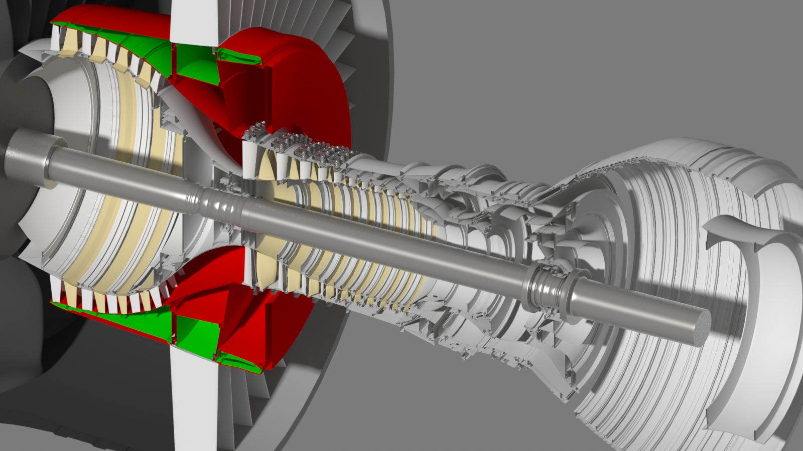
UPDATE - Summer of 2013 - Thanks to new data from GE, I'm rebuilding this engine for much greater accuracy.
The rebuild article starts here.
The B787 project continues on the next page.
Click the "Page 03" link below, to continue...